Gigabyte GA-B250M-Gaming 5 Users Manual - Page 20
CLR_CMOS Clear CMOS Jumper, LED_C RGB RGBW LED Strip Extension Cable Header, BIOS Setup.
 |
View all Gigabyte GA-B250M-Gaming 5 manuals
Add to My Manuals
Save this manual to your list of manuals |
Page 20 highlights
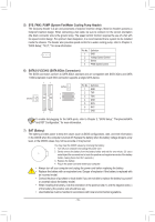
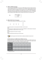
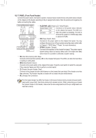
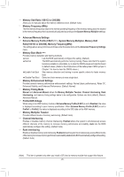
S F S _S S_ _ B _U U _ __ 3 B 15) CLR_CMOS (Clear CMOS Jumper) Use this jumper to clear the BIOS configuration and resFe_tUtShBe3 CFMOS values to factory defaults. To clear the CMOS values, use a metal object like a screwdriver to touch the two pins for a few seconds. _ Open: Normal Short: Clear CMOS Values _ _B _ •• Always turn off your computer and unplug the power cord from the power outlet before clearing the CMOS values. •• After system restart, go to BIOS Setup to load factory defaults (select Load Optimized Defaults) or manually configure the BIOS settings (refer to Chapter 2, "BIOS Setup," for BIOS configurations). 16) LED_C (RGB (RGBW) LED Strip Extension Cable Header) The header can be used to connect a standard 5050 RGB (RGBW) LED strip (12V/G/R/B/W), with maximum power rating of 2A (12V) and maximum length of 2m. _ 1 Black wire Pin No. 1 2 3 4 5 Definition 12V G R B W USB 0_ B 12V of the LED strip 1 12V Connect one end of the RGB (RGBW) LED strip extension cable to the header and the other end to your RGB (RGBW) LED strip. The black wire (marked with a triangle on the plug) of the extension cable must be connected to Pin 1 (12V) of this header. The 12V pin (marked with an arrow) on the other end of the extension cable must be lined up with the 12V of the LED strip. Be careful with the connection orientation of the LED strip; incorrect connection may lead to the damage of the LED strip. For how to turn on/off the lights of the RGB (RGBW) LED strip, refer to the instructions on in Chapter 2, "BIOS Setup." B_ Before installing the devices, be sure to turn off the devices and your computer. Unplug the power cord from the power outlet to prevent damage to the devices. F _0 _F _0 F - 20 -
-
 1
1 -
2
-
3
-
4
-
5
-
6
-
7
-
8
-
9
-
10
-
11
-
12
-
13
-
14
-
 15
15 -
 16
16 -
 17
17 -
 18
18 -
 19
19 -
 20
20 -
 21
21 -
 22
22 -
 23
23 -
 24
24 -
 25
25 -
26
-
27
-
28
-
29
-
30
-
31
-
32
-
33
-
34
-
35
-
36
-
37
-
38
-
39
-
40
-
41
-
42
-
43
-
44
 |
 |