Gigabyte GA-B75-DS3V Manual - Page 14
CPU_FAN/SYS_FAN1/2/3 Fan Headers, SATA3 0 SATA 6Gb/s Connector
 |
View all Gigabyte GA-B75-DS3V manuals
Add to My Manuals
Save this manual to your list of manuals |
Page 14 highlights
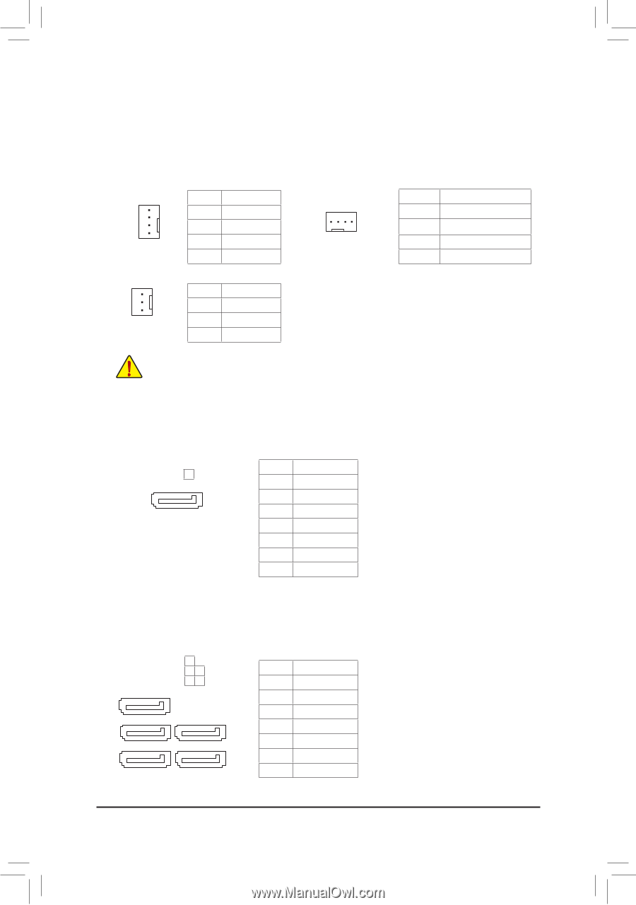
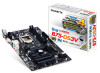
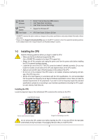
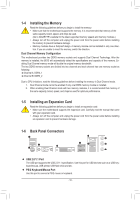
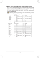
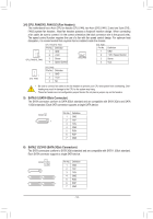
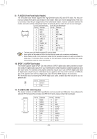
3/4) CPU_FAN/SYS_FAN1/2/3 (Fan Headers) The motherboard has a 4-pin CPU fan header (CPU_FAN), two 4-pin (SYS_FAN1, 2) and one 3-pin (SYS_ FAN3) system fan headers.. Most fan headers possess a foolproof insertion design. When connecting a fan cable, be sure to connect it in the correct orientation (the black connector wire is the ground wire). The speed control function requires the use of a fan with fan speed control design. For optimum heat dissipation, it is recommended that a system fan be installed inside the chassis. 1 CPU_FAN/SYS_FAN2 CPU_FAN/SYS_FAN2: Pin No. Definition 1 GND 2 +12V 3 Sense 4 Speed Control 1 SYS_FAN1 SYS_FAN1: Pin No. 1 2 3 4 Definition GND +12V / Speed Control Sense VCC 1 SYS_FAN3 SYS_FAN3: Pin No. Definition 1 GND 2 +12V 3 NC DEBUG PORT •• Be sure to connect fan cables to the fan headers to prevent your CPU and system from overheating. Overheating may result in damage to the CPU or the system may hang. •• These fan headers are not configuration jumper blocks. Do not place a jumper cap on the headers. 5) SATA3 0 (SATA 6Gb/s Connector) The SATA connectors conform to SATA 6Gb/s standard and are compatible with SATA 3Gb/s and SATA 1.5Gb/s standard. Each SATA connector supports a single SATA device. SATA3 0 1 7 Pin No. Definition 1 GND DEBUG 2 TXP PORT 3 TXN DEBUG 4 PORT 5 DEBUG PORT 6 7 DGEBNUDG PRORXTN DPROEBXRUTPG GND 6) SATA2 1/2/3/4/5 (SATA 3Gb/s Connectors) The SATA connectors conform to SATA 3Gb/s standard and are compatible with SATA 1.5Gb/s standard. Each SATA connector supports a single SATA device. 1 SATA2 3 2 54 Pin No. Definition 1 GND 1 7 2 TXP 3 TXN 1 7 4 GND 5 RXN 1 7 6 RXP 7 GND - 14 -
-
 1
1 -
2
-
3
-
4
-
5
-
6
-
7
-
8
-
 9
9 -
 10
10 -
 11
11 -
 12
12 -
 13
13 -
 14
14 -
 15
15 -
 16
16 -
 17
17 -
 18
18 -
 19
19 -
20
-
21
-
22
-
23
-
24
-
25
-
26
-
27
-
28
-
29
-
30
-
31
-
32
-
33
-
34
-
35
-
36
 |
 |