Gigabyte GA-B75-DS3V Manual - Page 16
F_AUDIO Front Panel Audio Header, SPDIF_O S/PDIF Out Header, F_USB30 USB 3.0/2.0 Header
 |
View all Gigabyte GA-B75-DS3V manuals
Add to My Manuals
Save this manual to your list of manuals |
Page 16 highlights
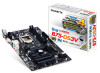
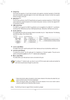
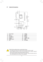
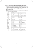
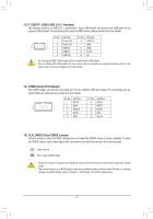
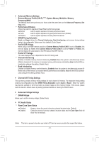
F_AUDIO(H) DB_PORT 9) F_AUDIO (Front Panel Audio Header) The front panel audio header supports Intel High Definition audio (HD) and AC'97 audio. You may con- nect your chassis front panel audio module to this header. Make sure the wire assignments of the mod- ule connector match the pin assignments of the motherboard header. Incorrect connection between the module connector and the motherboard header will make the device unable to work or even damage it. For HD Front Panel Audio: For AC'97 Front Panel Audio: Pin No. Definition Pin No. Definition 9 1 1 MIC2_L F_PA2NEL(NHG)ND 3 MIC2_R 1 MIC 2 GND F_PANEL 3 MIC Power (H61M-D2) 10 2 4 -ACZ_DET 5 LINE2_R 4 NC 5 Line Out (R) 6 GND 6 NC 7 FAUDIO_JD 7 NC 8 No Pin 8 No Pin 9 LINE2_L 9 Line Out (L) 10 GND 10 NC •• The front panel audio header supports HD audio by default. BIO•S• SAwuitdchioers(iXg5n8aAls-OwCi)ll be present on both of the front and back panel audio connections simultaneously. •• 1Some chassis provide a front panel audio module that has separated connectors on each wire instead of a single plug. For information about connecting the front panel audio module that has different wire assignments, please contacMt_tShAeTcAhassis manufacturer. 1 DIP 1 23 1 DIP 1 23 1 10) SPDIF_O (S/PDIF Out Header) ACPI_CPT age measurement module(X58A-OC) This header supports digital S/PDIF Out and connects a S/PDIF digital aud(GioA-cIVaBb)le (provided by expan- sion caPrWdMs)Sfwoitrchdi(gX5it8aAl-OauC)dio output from your motherboard to certain expansion cards like graphics cards and sound cards. For example, some graphics cards may require you to use a S/PDIF digital audio cable for digital audio output from your motherboard to your graphics card if you wish to connect an HDMI dis- play to the graphics card and have digital audio output from the HDMI display at the same time. DIP DIP 1 23 For information 1 23 about connecting the S/PDIF digital audio cable, carefully SrMeaBd_CtPhTe manual for your ex- pansion card. (GA-IVB) PCIe power connector (SATA)(X58A-OC) Pin No. Definition 1 SPDIFO 1 2 GND CLR_CMOS 11) F_USB30 (USB 3.0/2.0 Header) CI The header conforms to USB 3.0/2.0 specification and can provide two USDGBIPS1_5pM_oECrPtsT. For purchasing the optional 3.5" front panel that provides two USB 3.0/2.0 ports, please contact(GthAe-IVlBo)cal dealer. F_USB30 BIOS Switcher (SW4) 20 1 11 10 Pin No. 1 2 3 4 5 6 7 8 9 10 Definition VBUS SSRX1SSRX1+ GND SSTX1SSTX1+ GND D1D1+ NC Pin No. 11 12 13 14 15 16 17 18 19 20 Definition D2+ D2GND SSTX2+ SSTX2GND SSRX2+ SSRX2VBUS No Pin XDP_CPU XDP_PCH (GA-IVB) F_AUDIO(H) DB_PORT - 16 - DIP 2345 PWM Switch (S BIOS_PH (GA-IVB)
-
 1
1 -
2
-
3
-
4
-
5
-
6
-
7
-
8
-
9
-
10
-
 11
11 -
 12
12 -
 13
13 -
 14
14 -
 15
15 -
 16
16 -
 17
17 -
 18
18 -
 19
19 -
 20
20 -
 21
21 -
22
-
23
-
24
-
25
-
26
-
27
-
28
-
29
-
30
-
31
-
32
-
33
-
34
-
35
-
36
 |
 |