Gigabyte GA-E350N-USB3 Manual - Page 31
MB Intelligent Tweaker(M.I.T.), UMA Frame Buffer Size - overclock
 |
UPC - 818313012081
View all Gigabyte GA-E350N-USB3 manuals
Add to My Manuals
Save this manual to your list of manuals |
Page 31 highlights
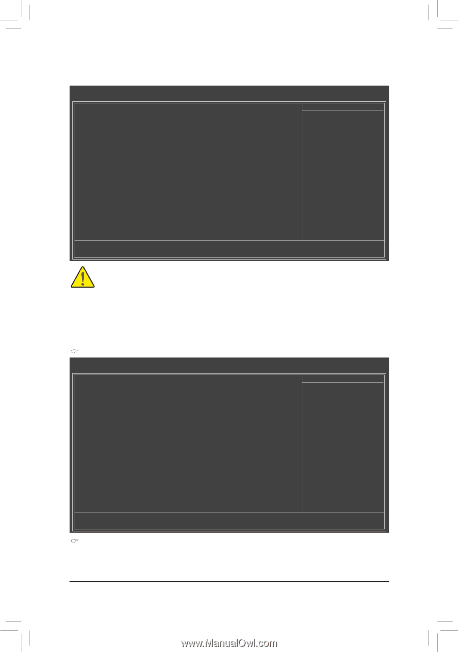
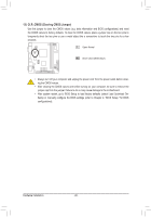
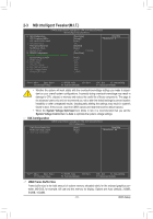
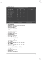
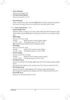
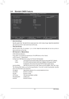
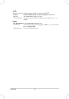
2-3 MB Intelligent Tweaker(M.I.T.) CMOS Setup Utility-Copyright (C) 1984-2010 Award Software MB Intelligent Tweaker(M.I.T.) } IGX Configuration CPU Frequency(MHz) CPU Host Clock Control x CPU Host Clock PCIe Spread Spectrum Set Memory Clock x Memory Clock } DRAM Configuration ******** System Voltage Optimized ******** System Voltage Control x DDR3 Voltage x FCH Voltage x PCIe PLL Voltage x CPU NB VID Control x CPU Voltage Control Normal CPU Vcore [Press Enter] [Normal] [Auto] 100 [Disabled] [Auto] x5.33 1066Mhz [Press Enter] [Auto] Auto Auto Auto Auto Auto 1.3500V Item Help Menu Level Move Enter: Select F5: Previous Values +/-/PU/PD: Value F10: Save F6: Fail-Safe Defaults ESC: Exit F1: General Help F7: Optimized Defaults • Whether the system will work stably with the overclock/overvoltage settings you made is dependent on your overall system configurations. Incorrectly doing overclock/overvoltage may result in damage to CPU, chipset, or memory and reduce the useful life of these components. This page is for advanced users only and we recommend you not to alter the default settings to prevent system instability or other unexpected results. (Inadequately altering the settings may result in system's failure to boot. If this occurs, clear the CMOS values and reset the board to default values.) • When the System Voltage Optimized item blinks in red, it is recommended that you set the System Voltage Control item to Auto to optimize the system voltage settings. IGX Configuration CMOS Setup Utility-Copyright (C) 1984-2010 Award Software IGX Configuration UMA Frame Buffer Size VGA Core Clock control x VGA Core Clock(MHz) [Auto] [Auto] 500 Item Help Menu Level Move Enter: Select F5: Previous Values +/-/PU/PD: Value F10: Save F6: Fail-Safe Defaults ESC: Exit F1: General Help F7: Optimized Defaults UMA Frame Buffer Size Frame buffer size is the total amount of system memory allocated solely for the onboard graphics controller. MS-DOS, for example, will use only this memory for display. Options are: Auto (default), 256MB, 512MB, 1024MB. - 31 - BIOS Setup
-
 1
1 -
2
-
3
-
4
-
5
-
6
-
7
-
8
-
9
-
10
-
11
-
12
-
13
-
14
-
15
-
16
-
17
-
18
-
19
-
20
-
21
-
22
-
23
-
24
-
25
-
 26
26 -
 27
27 -
 28
28 -
 29
29 -
 30
30 -
 31
31 -
 32
32 -
 33
33 -
 34
34 -
 35
35 -
 36
36 -
37
-
38
-
39
-
40
-
41
-
42
-
43
-
44
-
45
-
46
-
47
-
48
-
49
-
50
-
51
-
52
-
53
-
54
-
55
-
56
-
57
-
58
-
59
-
60
-
61
-
62
-
63
-
64
-
65
-
66
-
67
-
68
-
69
-
70
-
71
-
72
-
73
-
74
-
75
-
76
-
77
-
78
-
79
-
80
 |
 |