Gigabyte GA-EP45T-UD3R Manual
Gigabyte GA-EP45T-UD3R Manual
 |
View all Gigabyte GA-EP45T-UD3R manuals
Add to My Manuals
Save this manual to your list of manuals |
Gigabyte GA-EP45T-UD3R manual content summary:
- Gigabyte GA-EP45T-UD3R | Manual - Page 1
GA-EP45T-UD3R/ GA-EP45T-UD3 LGA775 socket motherboard for Intel® CoreTM processor family/ Intel® Pentium® processor family/Intel® Celeron® processor family User's Manual Rev. 1002 12ME-EP45TUD3R-1002R - Gigabyte GA-EP45T-UD3R | Manual - Page 2
Motherboard GA-EP45T-UD3R/GA-EP45T-UD3 Oct. 2, 2008 Motherboard GA-EP45T-UD3R/ GA-EP45T-UD3 Oct. 2, 2008 - Gigabyte GA-EP45T-UD3R | Manual - Page 3
with the product. For detailed product information, carefully read the User's Manual. For instructions on how to use GIGABYTE's unique features, read or download the information on/from the Support\Motherboard\Technology Guide page on our website. For product-related information, check on our - Gigabyte GA-EP45T-UD3R | Manual - Page 4
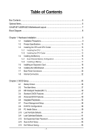
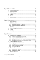
...6 GA-EP45T-UD3R/UD3 Motherboard Layout 7 Block Diagram...8 Chapter 1 Hardware Installation 9 1-1 Installation Precautions 9 1-2 Product Specifications 10 1-3 Installing the CPU and CPU Cooler 13 1-3-1 Installing the CPU 13 1-3-2 Installing the CPU Cooler 15 1-4 Installing the Memory 16 - Gigabyte GA-EP45T-UD3R | Manual - Page 5
105 5-2-2 Installing the S/PDIF In Cable (Optional 107 5-2-3 Configuring Microphone Recording 108 5-2-4 Using the Sound Recorder 110 5-3 Troubleshooting 111 5-3-1 Frequently Asked Questions 111 5-3-2 Troubleshooting Procedure 112 5-4 Regulatory Statements 114 Only for GA-EP45T-UD3R. - 5 - - Gigabyte GA-EP45T-UD3R | Manual - Page 6
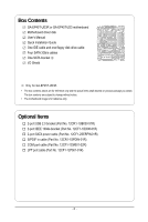
Box Contents GA-EP45T-UD3R or GA-EP45T-UD3 motherboard Motherboard driver disk User's Manual Quick Installation Guide One IDE cable and one floppy disk drive cable Four SATA 3Gb/s cables One SATA bracket I/O Shield Only for GA-EP45T-UD3R. • The box contents above are for reference only and the - Gigabyte GA-EP45T-UD3R | Manual - Page 7
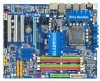
SPDIF_I PCI2 PCI3 CD_IN Intel® P45 IDE SYS_FAN2 GIGABYTE Intel® ICH10R SATA2 Intel® ICH10 SATA2_4 SATA2_2 SATA2_0 SATA2_5 SATA2_3 SATA2_1 TSB43AB23 FDD F1_1394 M_BIOS B_BIOS PWR_LED CLR_CMOS COMA LPT F_USB2 F_USB1 F_PANEL Only for GA-EP45T-UD3R. Only for GA-EP45T-UD3. - 7 - - Gigabyte GA-EP45T-UD3R | Manual - Page 8
x1 x1 LAN RJ45 RTL 8111C x1 PCI Express Bus 2 SATA 3Gb/s ATA-133/100/66/ 33 IDE Channel PCI Bus GIGABYTE SATA2 TSB43AB23 3 IEEE 1394a Host Interface DDR3 2200/1600/1333/ 1066/800 MHz Intel® P45 Dual Channel Memory MCH CLK (400/333/266/200 MHz) Intel® ICH10R Intel® ICH10 Dual BIOS 6 SATA - Gigabyte GA-EP45T-UD3R | Manual - Page 9
's manual and follow these procedures: • Prior to installation, do not remove or break motherboard S/N wrist strap when handling electronic components such as a motherboard, CPU or memory. If you do not have an ESD wrist steps or have a problem related to the use of the product, please consult - Gigabyte GA-EP45T-UD3R | Manual - Page 10
® P45 Express Chipset South Bridge: Intel® ICH10R / ICH10 4 x 1.5V DDR3 DIMM sockets supporting up to 16 GB of system memory (Note 1) Dual channel memory architecture Support for DDR3 2200/1600/1333/1066/800 MHz memory modules (Go to GIGABYTE's website for the latest memory support list - Gigabyte GA-EP45T-UD3R | Manual - Page 11
USB Integrated in the South Bridge Up to 12 USB 2.0/1.1 ports (8 on the back panel, 4 via the USB brackets connected to the internal USB headers) Internal Connectors 1 x 24-pin ATX main power connector 1 x 8-pin ATX 12V power connector 1 x floppy disk drive connector 1 x IDE connector - Gigabyte GA-EP45T-UD3R | Manual - Page 12
, the actual memory size displayed will be less than 4 GB. (Note 2) Whether the CPU/System fan speed control function is supported will depend on the CPU/ System cooler you install. (Note 3) Available functions in EasyTune may differ by motherboard model. GA-EP45T-UD3R/UD3 Motherboard - 12 - - Gigabyte GA-EP45T-UD3R | Manual - Page 13
the CPU: • Make sure that the motherboard supports the CPU. (Go to GIGABYTE's website for the latest CPU support list.) • Always turn off the computer the CPU, graphics card, memory, hard drive, etc. 1-3-1 Installing the CPU A. Locate the alignment keys on the motherboard CPU socket and the notches - Gigabyte GA-EP45T-UD3R | Manual - Page 14
B. Follow the steps below to correctly install the CPU into the motherboard CPU socket. Before installing the CPU, make sure to turn off the computer and unplug inserted, replace the load plate and push the CPU socket lever back into its locked position. GA-EP45T-UD3R/UD3 Motherboard - 14 - - Gigabyte GA-EP45T-UD3R | Manual - Page 15
that the Male and Female push pins are joined closely. (Refer to your CPU cooler installation manual for instructions on installing the cooler.) Step 5: After the installation, check the back of the motherboard. If the push pin is inserted as the picture above, the installation is complete. Step - Gigabyte GA-EP45T-UD3R | Manual - Page 16
, a message which says memory is operating in Flex Memory Mode will appear during the POST. Intel ® Flex Memory Technology offers greater flexibility to upgrade by allowing dif ferent memory sizes to be populated and remain in Dual Channel mode/performance. GA-EP45T-UD3R/UD3 Motherboard - 16 - - Gigabyte GA-EP45T-UD3R | Manual - Page 17
unplug the power cord from the power outlet to prevent damage to the memory module. DDR3 and DDR2 DIMMs are not compatible to each other or DDR DIMMs. Be sure to install DDR3 DIMMs on this motherboard. Notch DDR3 DIMM A DDR3 memory module has a notch, so it can only fit in one direction. Follow the - Gigabyte GA-EP45T-UD3R | Manual - Page 18
expansion card: • Make sure the motherboard supports the expansion card. Carefully read the manual that came with your expansion card. necessary, go to BIOS Setup to make any required BIOS changes for your expansion card(s). 7. Install the driver provided with the GA-EP45T-UD3R/UD3 Motherboard - 18 - - Gigabyte GA-EP45T-UD3R | Manual - Page 19
a screw. Step 2: Connect the SA TA cable from the bracket to the SATA port on your motherboard. Step 3: Step 4: Connect the power Plug one end of the cable from the bracket SATA signal enclosure. The SATA bracket is included with the GA-EP45T -UD3R only. - 19 - Hardware Installation - Gigabyte GA-EP45T-UD3R | Manual - Page 20
The USB port supports the USB 2.0/1.1 LAN port LEDs. Connection/ Speed LED Activity LED LAN motherboard. • When removing the cable, pull it straight out from the connector. Do not rock it side to side to prevent an electrical short inside the cable connector. GA-EP45T-UD3R/UD3 Motherboard - Gigabyte GA-EP45T-UD3R | Manual - Page 21
to perform different functions via the audio software. Only microphones still MUST be connected to the default Mic in jack ( ). Refer to the instructions on setting up a 2/4/5.1/ 7.1-channel audio configuration in Chapter 5, "Configuring 2/4/5.1/7.1-Channel Audio." - 21 - Hardware Installation - Gigabyte GA-EP45T-UD3R | Manual - Page 22
devices. • After installing the device and before turning on the computer, make sure the device cable has been securely attached to the connector on the motherboard. GA-EP45T-UD3R/UD3 Motherboard - 22 - - Gigabyte GA-EP45T-UD3R | Manual - Page 23
2x12 Main Power Connector) With the use of the power connector, the power supply can supply enough stable power to all the components on the motherboard. Before connecting the power connector, first make sure the power supply is turned off and all devices are properly installed. The power connector - Gigabyte GA-EP45T-UD3R | Manual - Page 24
to connect it in the correct orientation (the black connector wire is the ground wire). The motherboard supports CPU fan speed control, which requires the use of a CPU fan with fan speed control - 3 MPD- System Status LED S0 On S1 Blinking S3/S4/S5 Off GA-EP45T-UD3R/UD3 Motherboard - 24 - - Gigabyte GA-EP45T-UD3R | Manual - Page 25
to connect a floppy disk drive. The types of floppy disk drives supported are: 360 KB, 720 KB, 1.2 MB, 1.44 MB, and 2.88 MB. Before connecting a floppy disk drive, be sure to locate pin the IDE devices, read the instructions from the device manufacturers.) 40 39 2 1 - 25 - Hardware Installation - Gigabyte GA-EP45T-UD3R | Manual - Page 26
SA TA 3Gb/s standard and are compatible with SA TA 1.5Gb/s standard. Each SATA connector supports a single SA TA device. SATA2_4 7 7 SATA2_5 SATA2_2 SATA2_3 SATA2_0 SATA2_1 Pin No. 1 2 3 4 5 6 7 Definition GND TXP TXN GND RXN RXP GND Only for GA-EP45T-UD3. GA-EP45T-UD3R/UD3 Motherboard - 26 - - Gigabyte GA-EP45T-UD3R | Manual - Page 27
with SA TA 1.5Gb/s standard. Each SATA connector supports a single SA TA device. The GIGABYTE SATA2 controller supports RAID 0 and RAID 1. Refer to Chapter 5, "Configuring SA TA Hard Drive(s)," for instructions on configuring a RAID array. Pin No. Definition 1 GND 17 2 TXP 3 TXN - Gigabyte GA-EP45T-UD3R | Manual - Page 28
a beep code. One single short beep will be heard if no problem is detected at system startup. If a problem is detected, the BIOS may issue beeps in different patterns to indicate the problem. Refer to Chapter 5, "Troubleshooting," for information about beep codes. • HD (Hard Drive Activity LED, Blue - Gigabyte GA-EP45T-UD3R | Manual - Page 29
the pin assignments of the motherboard header. Incorrect connection between the module connector and the motherboard header will make the device panel audio header supports HD audio by default. If your chassis provides an AC'97 front panel audio module, refer to the instructions on how to activate - Gigabyte GA-EP45T-UD3R | Manual - Page 30
This header supports digital S/PDIF out and connects a S/PDIF digital audio cable (provided by expansion cards) for digital audio output from your motherboard to certain carefully read the manual for your expansion card. Pin No. Definition 1 SPDIFO 1 2 GND GA-EP45T-UD3R/UD3 Motherboard - 30 - - Gigabyte GA-EP45T-UD3R | Manual - Page 31
16) F_USB1/F_USB2 (USB Headers, Yellow) The headers conform to USB 2.0/1.1 specification. Each USB header can provide two USB ports via an optional USB bracket. For purchasing the optional USB bracket, please contact the local dealer. 9 1 10 2 Pin No. 1 2 3 4 5 6 7 8 9 10 Definition Power (5V) - Gigabyte GA-EP45T-UD3R | Manual - Page 32
COM port cable. For purchasing the optional COM port cable, please contact the local dealer. 9 1 10 2 Pin No. 1 2 3 4 5 6 7 8 9 10 Definition NDCDNSIN NSOUT NDTRGND NDSRNRTSNCTSNRINo Pin GA-EP45T-UD3R/UD3 Motherboard - 32 - - Gigabyte GA-EP45T-UD3R | Manual - Page 33
the jumper. Failure to do so may cause damage to the motherboard. • After system restart, go to BIOS Setup to load factory defaults (select Load Optimized Defaults) or manually configure the BIOS settings (refer to Chapter 2, "BIOS Setup," for BIOS configurations). - 33 - Hardware Installation - Gigabyte GA-EP45T-UD3R | Manual - Page 34
22) BAT (BATTERY) The battery provides power to keep the values (such as BIOS configurations, date, and time information) in the CMOS when the computer is turned off. Energy Saver Advanced. Refer to Chapter 4, "Dynamic Energy Saver Advanced," for more details. GA-EP45T-UD3R/UD3 Motherboard - 34 - - Gigabyte GA-EP45T-UD3R | Manual - Page 35
that searches and downloads the latest version of BIOS from the Internet and updates the BIOS. For instructions on using the Q-Flash and @BIOS utilities, refer to Chapter 4, "BIOS Update Utilities." • Because BIOS flashing is potentially risky, if you do not encounter problems using the current - Gigabyte GA-EP45T-UD3R | Manual - Page 36
device boot order will still be based on BIOS Setup settings. You can access Boot Menu again to change the first boot device setting as needed. : Q-FLASH Press the key to access the Q-Flash utility directly without having to enter BIOS Setup first. GA-EP45T-UD3R/UD3 Motherboard - 36 - - Gigabyte GA-EP45T-UD3R | Manual - Page 37
to accept or enter a sub-menu. (Sample BIOS Version: GA-EP45T-UD3R E2) CMOS Setup Utility-Copyright (C) 1984-2008 Award Software MB Intelligent Tweaker(M.I.T.) Standard CMOS Features Advanced BIOS Features Integrated Peripherals Power Management Setup PnP/PCI Configurations - Gigabyte GA-EP45T-UD3R | Manual - Page 38
and exit BIOS Setup. (Pressing can also carry out this task.) Exit Without Saving Abandon all changes and the previous settings remain in effect. Pressing to the confirmation message will exit BIOS Setup. (Pressing can also carry out this task.) GA-EP45T-UD3R/UD3 Motherboard - 38 - Gigabyte GA-EP45T-UD3R | Manual - Page 39
Setup Utility-Copyright (C) 1984-2008 Award Software MB Intelligent Tweaker(M.I.T.) Memory Frequency (Mhz) DRAM Timing Selectable >>>>> Standard install a CPU that supports this feature. (Note 2) This item appears only if you install a memory module that supports this feature. - 39 - BIOS Setup - Gigabyte GA-EP45T-UD3R | Manual - Page 40
memory. Auto allows the BIOS overclocking, please wait for 20 seconds to allow for automated system reboot, or clear the CMOS values to reset the board to default values. (Default: Disabled) (Note) This item appears only if you install a CPU that supports this feature. GA-EP45T-UD3R/UD3 Motherboard - Gigabyte GA-EP45T-UD3R | Manual - Page 41
with the CPU specifications. PCI Express Frequency (Mhz) Allows you to manually set the PCIe clock frequency. The adjustable range is from 90 MHz when system instability occurs after overclocking, lower the overclocking ratio. >>>>> Advanced Clock Control Optimized Defaults - 41 - BIOS Setup - Gigabyte GA-EP45T-UD3R | Manual - Page 42
System Memory Multiplier settings. DRAM Timing Selectable (SPD) Manual allows all DRAM timing control items below to be configurable. Options are: Auto (default), Manual. (Note) This item appears only if you install a memory module that supports this feature. GA-EP45T-UD3R/UD3 Motherboard - 42 - Gigabyte GA-EP45T-UD3R | Manual - Page 43
: Auto (default), 1~255. tRTP Options are: Auto (default), 1~15. Command Rate(CMD) Options are: Auto (default), 1~3. ******** ESC: Exit F1: General Help F7: Optimized Defaults - 43 - BIOS Setup - Gigabyte GA-EP45T-UD3R | Manual - Page 44
Control Options are: Auto (default), +800ps~-700ps. DIMM2 Clock Skew Control Options are: Auto (default), +800ps~-700ps. ESC: Exit F1: General Help F7: Optimized Defaults GA-EP45T-UD3R/UD3 Motherboard - 44 - - Gigabyte GA-EP45T-UD3R | Manual - Page 45
Disables this function. Enabled Enables this function to enhance memory compatibility. DDR Write Training Allows you to determine whether to fine-tune memory parameters to enhance memory compatibility. Auto Lets the BIOS decide whether to enable this function. (Default) Disabled Disables - Gigabyte GA-EP45T-UD3R | Manual - Page 46
. The default is Auto. Ch-B Data VRef. The default is Auto. Ch-A Address VRef. The default is Auto. Ch-B Address VRef. The default is Auto. GA-EP45T-UD3R/UD3 Motherboard - 46 - - Gigabyte GA-EP45T-UD3R | Manual - Page 47
[None] [None] [None] [None] [None] [None] Drive A Floppy 3 Mode Support [1.44M, 3.5"] [Disabled] Halt On [All, But Keyboard] Move Enter: Select F5: Previous : General Help F7: Optimized Defaults Base Memory Extended Memory Total Memory CMOS Setup Utility-Copyright (C) 1984-2008 BIOS Setup - Gigabyte GA-EP45T-UD3R | Manual - Page 48
manually Mode Support Allows BIOS POST. Base Memory Also called conventional memory. Typically, 640 KB will be reserved for the MS-DOS operating system. Extended Memory The amount of extended memory. Total Memory The total amount of memory installed on the system. GA-EP45T-UD3R/UD3 Motherboard - Gigabyte GA-EP45T-UD3R | Manual - Page 49
(Note) No-Execute Memory Protect (Note) CPU Enhanced Halt (C1E) (Note) C2/C2E State Support (Note) x C4/C4E State Support (Note) CPU Thermal -HDD, Legacy LAN, Disabled. Password Check Specifies whether a password is required every time the system boots, or only when you enter BIOS Setup. After - Gigabyte GA-EP45T-UD3R | Manual - Page 50
system such as Windows NT4.0. (Default: Disabled) No-Execute Memory Protect (Note) Enables or disables Intel® Execute Disable Bit function CPU that supports this feature. For more information about Intel CPUs' unique features, please visit Intel's website. GA-EP45T-UD3R/UD3 Motherboard - 50 - Gigabyte GA-EP45T-UD3R | Manual - Page 51
Allows you to set a delay time for the BIOS to initialize the hard drive as the system boots up. The adjustable range is from 0 to 15 seconds. (Default: 0) Full Screen LOGO Show Allows you to determine whether to display the GIGABYTE Logo at system startup. Disabled displays normal POST message - Gigabyte GA-EP45T-UD3R | Manual - Page 52
RAID/AHCI Mode (Intel ICH10R Southbridge) Enables or disables RAID for the SA TA controllers integrated in the Intel ICH10R driver support Native mode. Only for GA-EP45T-UD3R. Only for GA-EP45T-UD3. (Note) Supported on Windows Vista operating system only. GA-EP45T-UD3R/UD3 Motherboard - Gigabyte GA-EP45T-UD3R | Manual - Page 53
Is Attached... If no LAN cable is attached to the motherboard, the Status fields of all four pairs of wires will show Open and the Length fields show 0m, as shown in the figure above. When LAN Cable Is Functioning Normally... If no cable problem is detected on the LAN cable connected to a Gigabit - Gigabyte GA-EP45T-UD3R | Manual - Page 54
LAN chip. (Default: Disabled) Onboard SATA/IDE Device (GIGABYTE SATA2 Chip) Enables or disables the IDE and SA TA controllers integrated in the GIGABYTE SA TA 2 chip. (Default: Enabled) Onboard SATA/IDE Ctrl Mode (GIGABYTE SATA2 Chip) Enables or disables RAID GA-EP45T-UD3R/UD3 Motherboard - 54 - - Gigabyte GA-EP45T-UD3R | Manual - Page 55
: Disabled) USB Storage Function Determines whether to detect USB storage devices, including USB flash drives and USB hard drives during the POST. (Default: Enabled) - 55 - BIOS Setup - Gigabyte GA-EP45T-UD3R | Manual - Page 56
Resume by Alarm x Date (of Month) Alarm x Time (hh:mm:ss) Alarm HPET Support (Note) x HPET Mode (Note) Power On By Mouse Power On By Keyboard x KB that supports wake-up function. (Default: Enabled) (Note) Supported on Windows® Vista® operating system only. GA-EP45T-UD3R/UD3 Motherboard - 56 - - Gigabyte GA-EP45T-UD3R | Manual - Page 57
, or the settings may not be effective. HPET Support (Note) Enables or disables High Precision Event Timer ® operating system. This item is configurable only if the HPET Support option is enabled. Select 32-bit mode when you install 32bit power. Memory The system returns to its last known awake state upon - Gigabyte GA-EP45T-UD3R | Manual - Page 58
,15 to the first PCI slot. BIOS auto-assigns IRQ to the second PCI slot. (Default) Assigns IRQ 3,4,5,7,9,10,11,12,14,15 to the second PCI slot. BIOS auto-assigns IRQ to the third PCI slot. (Default) Assigns IRQ 3,4,5,7,9,10,11,12,14,15 to the third PCI slot. GA-EP45T-UD3R/UD3 Motherboard - 58 - - Gigabyte GA-EP45T-UD3R | Manual - Page 59
the detection status of the chassis intrusion detection device attached to the motherboard CI header. If the system chassis cover is removed, this field will threshold for CPU temperature. When CPU temperature exceeds the threshold, BIOS will emit warning sound. Options are: Disabled (default), 60 - Gigabyte GA-EP45T-UD3R | Manual - Page 60
item is configurable only if Control is set to Enabled or Auto. CPU Smart FAN Auto Lets BIOS autodetect the type of CPU fan installed and sets the optimal CPU fan control mode. (Default) selecting PWM mode may not effectively reduce the fan speed. GA-EP45T-UD3R/UD3 Motherboard - 60 - - Gigabyte GA-EP45T-UD3R | Manual - Page 61
to load Fail-Safe defaults, which are the safest and most stable BIOS settings for the motherboard. 2-11 Load Optimized Defaults CMOS Setup Utility-Copyright (C) 1984-2008 Award Software MB Intelligent Tweaker(M.I.T.) Load Fail-Safe Defaults Standard CMOS Features Load Optimized Defaults - Gigabyte GA-EP45T-UD3R | Manual - Page 62
you to view the BIOS settings but not to make changes. To clear the password, press on the password item and when requested for the password, press again. The message "PASSWORD DISABLED" will appear, indicating the password has been cancelled. GA-EP45T-UD3R/UD3 Motherboard - 62 - - Gigabyte GA-EP45T-UD3R | Manual - Page 63
2-13 Save & Exit Setup CMOS Setup Utility-Copyright (C) 1984-2008 Award Software MB Intelligent Tweaker(M.I.T.) Load Fail-Safe Defaults Standard CMOS Features Load Optimized Defaults Advanced BIOS Features Set Supervisor Password Integrated Peripherals Save to CMOS and EXIT (SYe/tNU - Gigabyte GA-EP45T-UD3R | Manual - Page 64
GA-EP45T-UD3R/UD3 Motherboard - 64 - - Gigabyte GA-EP45T-UD3R | Manual - Page 65
other drivers. • After the drivers are installed, follow the onscreen instructions to restart your system. You can install other applications included in the motherboard driver disk. • For USB 2.0 driver support under the Windows XP operating system, please install the Windows XP Service Pack - Gigabyte GA-EP45T-UD3R | Manual - Page 66
that GIGABYTE develops and some free software. You can click the Install button on the right of an item to install it. 3-3 Technical Manuals This page provides GIGABYTE's application guides, content descriptions for this driver disk, and the motherboard manuals. GA-EP45T-UD3R/UD3 Motherboard - 66 - Gigabyte GA-EP45T-UD3R | Manual - Page 67
3-4 Contact Click the URL on this page to link to the GIGABYTE Web site. Or read the last page of th is manual to check the contact information for GIGABYTE Taiwan headquarter or worldwide branch of fices. 3-5 System This page provides the basic system information. - 67 - Drivers Installation - Gigabyte GA-EP45T-UD3R | Manual - Page 68
3-6 Download Center To update the BIOS, drivers, or applications, click the Download Center button to link to the GIGABYTE Web site. The latest version of the BIOS, drivers, or applications will be displayed. GA-EP45T-UD3R/UD3 Motherboard - 68 - - Gigabyte GA-EP45T-UD3R | Manual - Page 69
system memory • VESA compatible graphics card • Windows® XP with SP1 or later • Xpress Recovery and Xpress Recovery2 are different utilities. For example, a backup file created with Xpress Recovery cannot be restored using Xpress Recovery2. • USB hard drives are not supported. • Hard drives in RAID - Gigabyte GA-EP45T-UD3R | Manual - Page 70
Drive 1. Set CD-ROM drive as the first boot device under "Advanced BIOS Features" in the BIOS Setup program. Save the changes and exit. 2. When partitioning your hard drive example, NTFS) and begin the installation of the operating system (Figure 3). Figure 3 GA-EP45T-UD3R/UD3 Motherboard - 70 - - Gigabyte GA-EP45T-UD3R | Manual - Page 71
4. After the operating system is installed, right-click the My Computer icon on your desktop and select Manage (Figure 4). Go to Computer Management to check disk allocation. Xpress Recovery2 will save the backup file to the unallocated space (black stripe along the top)(Figure 5). Please note that - Gigabyte GA-EP45T-UD3R | Manual - Page 72
from the motherboard driver disk to Inc. EP45T-UD3R E2 . . . . : BIOS Setup : XpressRecovery2 : Boot Menu : Qflash 09/22/2008-P45-ICH10-7A69PG02C Management to check disk allocation. Figure 12 GA-EP45T-UD3R/UD3 Motherboard Xpress Recovery2 will automatically create a new partition - Gigabyte GA-EP45T-UD3R | Manual - Page 73
D. Using the Restore Function in Xpress Recovery2 Select RESTORE to restore the backup to your hard drive in case the system breaks down. The RESTORE option will not be present if no backup is created before (Figure 13, 14). Figure 13 Figure 14 E. Removing the Backup 1. If you wish to remove the - Gigabyte GA-EP45T-UD3R | Manual - Page 74
, Inc. EP45T-UD3R E2 . . . . : BIOS Setup : XpressRecovery2 : Boot Menu : Qflash 09/22/2008-P45-ICH10-7A69PG02C-00 Because BIOS flashing is potentially risky, please do it with caution. Inadequate BIOS flashing may result in system malfunction. GA-EP45T-UD3R/UD3 Motherboard - 74 - Gigabyte GA-EP45T-UD3R | Manual - Page 75
and press . • The Save Main BIOS to Drive option allows you to save the current BIOS file. • Q-Flash only supports USB flash drive or hard drives using F AT32/16/12 file system. • If the BIOS update file is saved to a hard drive in RAID/AHCI mode or a hard drive attached to an independent - Gigabyte GA-EP45T-UD3R | Manual - Page 76
F11: Save CMOS to BIOS F12: Load CMOS from BIOS Load Optimized Defaults Press to load BIOS defaults Step 6: Select Save & Exit Setup and then press to save settings to CMOS and exit BIOS Setup. The procedure is complete after the system restarts. GA-EP45T-UD3R/UD3 Motherboard - 76 - - Gigabyte GA-EP45T-UD3R | Manual - Page 77
location and then download the BIOS file that matches your motherboard model. Follow the on- screen instructions to complete. If the BIOS update file for your motherboard is not present on the @BIOS server site, please manually download the BIOS update file from GIGABYTE's website and follow - Gigabyte GA-EP45T-UD3R | Manual - Page 78
hardware components such as CPU, chipset, and memory and reduce the useful life of these components. Before you do the overclock/overvoltage, make sure that you fully know each function of EasyTune 6, or system instability or other unexpected results may occur. GA-EP45T-UD3R/UD3 Motherboard - 78 - - Gigabyte GA-EP45T-UD3R | Manual - Page 79
and software design, GIGABYTE Dynamic Energy Saver A. Meter Mode In Meter Mode, GIGABYTE Dynamic Energy Saver Advanced shows how Energy Saver On/Off Switch (Default: Off) 2 Motherboard Phase LED On/Off Switch (Default: On) 3 depending on motherboard model. • CPU Power and Power Scores are for - Gigabyte GA-EP45T-UD3R | Manual - Page 80
DES function, make sure the CPU Enhanced Halt (C1E) and CPU EIST Function items in the BIOS Setup program are set to Enabled. (Note 2) Maximize system power saving with Dynamic Frequency Function; reset when the total power saving reaches 99999999 Watts. GA-EP45T-UD3R/UD3 Motherboard - 80 - - Gigabyte GA-EP45T-UD3R | Manual - Page 81
configuring your LAN connection settings and Q-Share, you are able to share your data with computers on the same network, making full use of Internet resources. Directions for using Q-Share After installing Q-Share from the motherboard driver disk, go to Start>All Programs>GIGABYTE> Q-Share.exe - Gigabyte GA-EP45T-UD3R | Manual - Page 82
and over 300 MB of available space. • Each storage volume can accommodate 64 shadow copies. When this limit is reached, the oldest shadow copy will be deleted and unable to be restored. Shadow copies are read-only so you cannot edit the contents of a shadow copy. GA-EP45T-UD3R/UD3 Motherboard - 82 - Gigabyte GA-EP45T-UD3R | Manual - Page 83
, on this motherboard, the SA TA2_0, SATA2_1, SATA2_2, SATA2_3, SATA2_4 and SATA2_5 ports are supported by ICH10R Southbridge.) Then connect the power connector from your power supply to the hard drive. Only for GA-EP45T-UD3R. (Note 1) Skip this step if you do not want to create RAID array on the - Gigabyte GA-EP45T-UD3R | Manual - Page 84
Step 2: Save changes and exit BIOS Setup. The BIOS Setup menus described in this section may differ from the exact settings for your motherboard. The actual BIOS Setup menu options you will see shall depend on the motherboard you have and the BIOS version. GA-EP45T-UD3R/UD3 Motherboard - 84 - - Gigabyte GA-EP45T-UD3R | Manual - Page 85
C. Configuring a RAID array in RAID BIOS Enter the RAID BIOS setup utility to configure a RAID array. Skip this step and proceed to the installation of Windows operating system for a non-RAID configuration. Step 1: After the POST memory test begins and before the operating system boot begins, look - Gigabyte GA-EP45T-UD3R | Manual - Page 86
RAID Level : Disks : Strip Size : Capacity : Volume0 RAID0(Stripe) Select Disks 128KB 223.6 GB Create Volume [ HELP ] The following are typical values: RAID0 - 128KB RAID10 - 64KB RAID5 - 64KB [ ]-Change [TAB]-Next [ESC]-Previous Menu Figure 5 [ENTER]-Select GA-EP45T-UD3R/UD3 Motherboard - Gigabyte GA-EP45T-UD3R | Manual - Page 87
(0) []-Select [ESC]-Exit Figure 7 [ENTER]-Select Menu To exit the ICH10R RAID BIOS utility , press or select Exit in MAIN MENU. Now, you may proceed to create the SA TA RAID/AHCI driver diskette and the installation of the SA TA RAID/ACHI driver and operating system. - 87 - Appendix - Gigabyte GA-EP45T-UD3R | Manual - Page 88
abort. Intel(R) Matrix Storage Manager option ROM v8.0.0.1039 ICH10R wRAID5 Copyright(C) 2003-08 Intel Corporation. All Rights Reversed. disks to non-RAID. WARNING: ALL DISK DATA WILL BE DELETED. [ ]-Select [ESC]-Previous Menu Figure 8 [DEL]-Delete Volume GA-EP45T-UD3R/UD3 Motherboard - 88 - - Gigabyte GA-EP45T-UD3R | Manual - Page 89
SATA port. (For example, on this motherboard, the GSA TA2_0 and GSATA2_1 ports are supported by GIGABYTE SA TA2.) Then connect the power connector from Peripherals SATA RAID/AHCI Mode SATA Port0-3 Native Mode Azalia Codec Onboard H/W 1394 Onboard H/W LAN Green LAN SMART LAN Onboard LAN Boot ROM - Gigabyte GA-EP45T-UD3R | Manual - Page 90
the POST memory test begins and before the operating system boot begins, look for a message which says "Press to enter RAID Setup Utility" (Figure 2). Press + to enter the GIGABYTE SATA2 RAID BIOS utility. GIGABYTE Technology Corp. PCIE-to-SATAII/IDE RAID Controller BIOS v1.06 - Gigabyte GA-EP45T-UD3R | Manual - Page 91
Array: In the main screen, press on the Create RAID Disk Drive item. Then the Create New RAID screen appears (Figure 4). GIGABYTE Technology Corp. PCIE-to-SATAII/IDE RAID Controller BIOS v1.06.78 [ Create New RAID ] [ Hard Disk Drive List ] Name: GRAID_ Level: 0-Stripe Disks: Select Disk - Gigabyte GA-EP45T-UD3R | Manual - Page 92
-RAID Confirm Creation [ RAID Disk Drive List ] [ Help ] Create RAID on the select HDD(Y/N)?Y CONFIRM RAID CREATION ALL DATA ON THE SELECTED HARD DISK WILL BE LOST WHEN EXIT WITH SAVING []-Switch Unit [DEL,BS]-Delete Number Figure 7 [ENTER]-Next [ESC]-Abort GA-EP45T-UD3R/UD3 Motherboard - Gigabyte GA-EP45T-UD3R | Manual - Page 93
will appear in the center of the screen (Figure 9). GIGABYTE Technology Corp. PCIE-to-SATAII/IDE RAID Controller BIOS v1.06.78 [ Main Menu ] [ Hard Disk Drive List ] Create RAID Disk Drive Delete RAID Disk Drive Revert HDD to Non-RAID Solve Mirror Conflict Rebuild Mirror Drive Save And Exit - Gigabyte GA-EP45T-UD3R | Manual - Page 94
RAID Inside [ RAID Disk Drive List ] Model Name RDD0: GRAID ALL DATA ON THE RAID WILL LOST!! ARE YOU SURE TO DELETE (Y/N)? N RAID Level Capacity Status 0-Stripe 240 GB Normal Members(HDDx) 01 []-Select RAID [SPACE]-Mark Delete [DEL]-Confirm Figure 11 GA-EP45T-UD3R/UD3 Motherboard - Gigabyte GA-EP45T-UD3R | Manual - Page 95
a startup disk: Use an alternative system and insert the motherboard driver disk. From your optical drive folder, double click the MENU.exe file in the BootDrv folder (Figure 3). A command prompt window will open similar to that in Figure 2. Only for GA-EP45T-UD3R. Figure 3 - 95 - Appendix - Gigabyte GA-EP45T-UD3R | Manual - Page 96
?" message, and then press to begin extracting the driver. After the driver is extracted, a screen similar to that in Figure 6 will appear. Figure 5 Figure 6 (Note) To install the Windows V ista 64-bit operating system, please copy the MSM64 file. GA-EP45T-UD3R/UD3 Motherboard - 96 - - Gigabyte GA-EP45T-UD3R | Manual - Page 97
RAID/AHCI driver diskette and configured the required BIOS RAID/AHCI driver and press (Figure 2). Windows Setup Setup could not determine the type of one or more mass storage devices installed in your system, or you have chosen to manually specify an adapter. Currently, Setup will load support - Gigabyte GA-EP45T-UD3R | Manual - Page 98
you do not have any device support disks from a mass storage device manufacturer, or do not want to specify additional mass storage devices for use with Windows, press ENTER. S=Specify Additional Device ENTER=Continue F3=Exit Figure 4 Only for GA-EP45T-UD3R. GA-EP45T-UD3R/UD3 Motherboard - 98 - - Gigabyte GA-EP45T-UD3R | Manual - Page 99
one of the items displayed and press . If you set the Onboard SATA/IDE Ctrl Mode item in BIOS Setup to RAID or AHCI mode, select (Windows XP/2003) RAID/AHCI Driver for GIGABYTE GBB36X Controller. Windows Setup You have chosen to configure a SCSI Adapter for use with Windows, using a device - Gigabyte GA-EP45T-UD3R | Manual - Page 100
Step 4: After the SATA RAID/AHCI driver installation is completed, you can proceed with the W indows XP installation. WindowsXP Professional Setup Welcome press R. To quit Setup without installing Windows XP, press F3. Enter= Continue R=Repair F3=Exit Figure 7 GA-EP45T-UD3R/UD3 Motherboard - 100 - - Gigabyte GA-EP45T-UD3R | Manual - Page 101
and perform standard OS installation steps. When a screen similar to that below appears, select Load Driver. (Figure 8). Figure 8 Step 2: Specify the location where the driver is saved, such as your floppy disk or USB flash drive (Figure 9). Figure 9 Only for GA-EP45T-UD3R. - 101 - Appendix - Gigabyte GA-EP45T-UD3R | Manual - Page 102
select Intel(R) ICH8R/ICH9R/ICH10R SATA RAID Controller (Note) and press Next. Figure 10 Step 4: After the driver is loaded, select the RAID/AHCI drive(s) where you shown as Intel(R) ICH10R SATA AHCI Controller when the SATA controllers are set to AHCI mode. GA-EP45T-UD3R/UD3 Motherboard - 102 - - Gigabyte GA-EP45T-UD3R | Manual - Page 103
GIGABYTE SATA2 controllers: Step 1: Restart your system to boot from the Windows Vista setup disk and perform standard OS installation steps. When a screen similar to that below appears (RAID/AHCI hard drive(s) will not be detected at this stage), select Load Driver (Figure 12). Figure 12 Step 2: - Gigabyte GA-EP45T-UD3R | Manual - Page 104
appears, select GIGABYTE GBB36X Controller and press Next. Figure 14 Step 4: After the driver is loaded, select the RAID/AHCI drive(s) where you want to install the operating system and then press Next to continue the OS installation (Figure 15). Figure 15 GA-EP45T-UD3R/UD3 Motherboard - 104 - - Gigabyte GA-EP45T-UD3R | Manual - Page 105
the Audio Control Panel. Before installing the audio driver, make sure the "Microsoft UAA Bus driver for High Definition Audio" has been installed from the motherboard driver disk and your operating system has been updated with the latest Service Pack for Windows. (Note) 2/4/5.1/7.1-Channel Audio - Gigabyte GA-EP45T-UD3R | Manual - Page 106
the Audio I/O tab. On the Connector Settings box, select the Mute rear panel output when front headphone plugged in check box. Click OK to complete. GA-EP45T-UD3R/UD3 Motherboard - 106 - - Gigabyte GA-EP45T-UD3R | Manual - Page 107
audio processing. A. Installing the S/PDIF In Cable: Step 1: First, attach the connector at the end of the cable to the SPDIF_I header on your motherboard. Step 2: Secure the metal bracket to the chassis back panel with a screw. S/PDIF Out: The S/PDIF out jacks can transmit audio signals to an - Gigabyte GA-EP45T-UD3R | Manual - Page 108
Click OK to complete the configuration. 5-2-3 Configuring Microphone Recording Step 1: After installing the audio driver, the Audio Manager icon will appear in your system tray. Doubleclick the icon to access and click it to open the volume control panel. GA-EP45T-UD3R/UD3 Motherboard - 108 - - Gigabyte GA-EP45T-UD3R | Manual - Page 109
Step 4: To hear the sound being recorded during the record- ing process when using the microphone function on or the front panel, do not select the Mute check box under Front Pink In or Front Green In in Master Volume. It is recommended that you set the volume at a middle level. To hear the - Gigabyte GA-EP45T-UD3R | Manual - Page 110
the Stop button . 5. You may use the Fast Forward button to move to the beginning of a file or the Fast Backward button to the end. GA-EP45T-UD3R/UD3 Motherboard - 110 - - Gigabyte GA-EP45T-UD3R | Manual - Page 111
5-3 Troubleshooting 5-3-1 Frequently Asked Questions To read more F AQs for your motherboard, please go to the Support\Motherboard\F AQ page on GIGABYTE's website. Q: In the BIOS Setup program, why are some BIOS options missing? A: Some advanced options are hidden in the BIOS Setup program. Press < - Gigabyte GA-EP45T-UD3R | Manual - Page 112
the memory into the memory socket. The problem is verified and solved. Press to enter BIOS Setup. Select "Load Fail-Safe Defaults" (or "Load Optimized Defaults"). Select "Save & Exit Setup" to save changes and exit BIOS Setup. A (Continued...) GA-EP45T-UD3R/UD3 Motherboard - 112 - Gigabyte GA-EP45T-UD3R | Manual - Page 113
Exit Setup" to save changes and exit BIOS Setup. No The keyboard or mouse might fail. The problem is verified and solved. Turn off the problem, contact the place of purchase or local dealer for help. Or go to the Support\Technical Service Zone page to submit your question. Our customer service - Gigabyte GA-EP45T-UD3R | Manual - Page 114
product. Restriction of Hazardous Substances (RoHS) Directive Statement GIGABYTE products have not intended to add and safe from office, your household waste disposal service or where you purchased the manual and we will be glad to help you with your effort. GA-EP45T-UD3R/UD3 Motherboard - 114 - - Gigabyte GA-EP45T-UD3R | Manual - Page 115
Finally, we suggest that you practice other environmentally friendly actions by understanding and using the energy-saving features of this product (where applicable), recycling the inner and outer packaging (including shipping containers) this product was delivered in, and by disposing of or - Gigabyte GA-EP45T-UD3R | Manual - Page 116
GA-EP45T-UD3R/UD3 Motherboard - 116 - - Gigabyte GA-EP45T-UD3R | Manual - Page 117
- 117 - Appendix - Gigabyte GA-EP45T-UD3R | Manual - Page 118
GA-EP45T-UD3R/UD3 Motherboard - 118 - - Gigabyte GA-EP45T-UD3R | Manual - Page 119
231, Taiwan TEL: +886-2-8912-4000 FAX: +886-2-8912-4003 Tech. and Non-Tech. Support (Sales/Marketing) : http://ggts.gigabyte.com.tw WEB address (English): http://www.gigabyte.com.tw WEB address (Chinese): http://www.gigabyte.tw G.B.T. INC. - U.S.A. TEL: +1-626-854-9338 FAX: +1-626-854-9339 Tech - Gigabyte GA-EP45T-UD3R | Manual - Page 120
in the language list on the top right corner of the website. GIGABYTE Global Service System To submit a technical or non-technical (Sales/ Marketing) question, please link to : http://ggts.gigabyte.com.tw Then select your language to enter the system. GA-EP45T-UD3R/UD3 Motherboard - 120 -
-
 1
1 -
 2
2 -
 3
3 -
 4
4 -
 5
5 -
 6
6 -
 7
7 -
8
-
9
-
10
-
11
-
12
-
13
-
14
-
15
-
16
-
17
-
18
-
19
-
20
-
21
-
22
-
23
-
24
-
25
-
26
-
27
-
28
-
29
-
30
-
31
-
32
-
33
-
34
-
35
-
36
-
37
-
38
-
39
-
40
-
41
-
42
-
43
-
44
-
45
-
46
-
47
-
48
-
49
-
50
-
51
-
52
-
53
-
54
-
55
-
56
-
57
-
58
-
59
-
60
-
61
-
62
-
63
-
64
-
65
-
66
-
67
-
68
-
69
-
70
-
71
-
72
-
73
-
74
-
75
-
76
-
77
-
78
-
79
-
80
-
81
-
82
-
83
-
84
-
85
-
86
-
87
-
88
-
89
-
90
-
91
-
92
-
93
-
94
-
95
-
96
-
97
-
98
-
99
-
100
-
101
-
102
-
103
-
104
-
105
-
106
-
107
-
108
-
109
-
110
-
111
-
112
-
113
-
114
-
115
-
116
-
117
-
118
-
119
-
120
 |
 |

GA-EP45T-UD3R/
GA-EP45T-UD3
LGA775 socket motherboard for Intel
®
Core
TM
processor family/
Intel
®
Pentium
®
processor family/Intel
®
Celeron
®
processor family
User's Manual
Rev. 1002
12ME-EP45TUD3R-1002R