Gigabyte GA-K8VNXP User Manual - Page 35
F1_1394 / F2_1394 Front IEEE1394 Connector
 |
View all Gigabyte GA-K8VNXP manuals
Add to My Manuals
Save this manual to your list of manuals |
Page 35 highlights
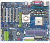
English 20) F1_1394 / F2_1394 (Front IEEE1394 Connector) Serial interface standard set by Institute of Electrical and Electronics Engineers, which has features like high speed, highbandwidth and hot plug. Be careful with the polarity of the IEEE1394 connector. Check the pin assignment carefully while you connect the IEEE1394 cable, incorrect connection between the cable and connector will make the device unable to work or even damage it. For optional IEEE1394 cable, please contact your local dealer. 2 16 F1_1394 2 10 1 9 Pin No. 1 2 3 4 5 6 7 8 9 10 Definition TPA2+ TPA2GND GND TPB2+ TPB2Power Power No Pin GND F2_1394 1 Pin No. 1 2 3 4 5 6 7 8 9 10 11 12 13 14 15 16 15 Definition Power Power TPA0+ TPA0GND GND TPB0+ TPB0Power Power TPA1+ TPA1GND No Pin TPB1+ TPB1- 21) IR Make sure the pin 1 on the IR device is aling with pin one the connector. To enable the IR function on the board, you are required to purchase an option IR module. Be careful with the polarity of the IR/CIR or IR connector. Check the pin assignment carefully while you connect the IR cable, incorrect connection between the cable and connector will make the device unable to work or even damage it. For optional IR cable, please contact your local dealer. Pin No. Definition 1 1 VCC(+5V) 2 No Pin 3 IR Data Input 4 GND 5 IR Data Output - 35 - Hardware Installation Process
-
 1
1 -
2
-
3
-
4
-
5
-
6
-
7
-
8
-
9
-
10
-
11
-
12
-
13
-
14
-
15
-
16
-
17
-
18
-
19
-
20
-
21
-
22
-
23
-
24
-
25
-
26
-
27
-
28
-
29
-
 30
30 -
 31
31 -
 32
32 -
 33
33 -
 34
34 -
 35
35 -
 36
36 -
 37
37 -
 38
38 -
 39
39 -
 40
40 -
41
-
42
-
43
-
44
-
45
-
46
-
47
-
48
-
49
-
50
-
51
-
52
-
53
-
54
-
55
-
56
-
57
-
58
-
59
-
60
-
61
-
62
-
63
-
64
-
65
-
66
-
67
-
68
-
69
-
70
-
71
-
72
-
73
-
74
-
75
-
76
-
77
-
78
-
79
-
80
-
81
-
82
-
83
-
84
-
85
-
86
-
87
-
88
-
89
-
90
-
91
-
92
-
93
-
94
-
95
-
96
-
97
-
98
-
99
-
100
-
101
-
102
-
103
-
104
-
105
-
106
-
107
-
108
-
109
-
110
-
111
-
112
 |
 |
