Gigabyte GA-M68MT-S2 Manual - Page 22
CKE Power Down Mode - no display
 |
View all Gigabyte GA-M68MT-S2 manuals
Add to My Manuals
Save this manual to your list of manuals |
Page 22 highlights
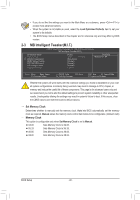
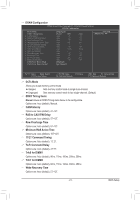
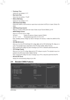
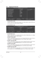
Precharge Time Options are: Auto (default), 4T~7T. Row Cycle Time Options are: Auto (default), 11T~42T. RAS to RAS Delay Options are: Auto (default), 4T~7T. CKE Power Down Mode Determines whether to set the memory to power down mode when the CKE pin is closed. (Default: Disabled) CKE Power Down Control Allows you to select a CKE power down mode. Options are per Channel (Default), per CS. DDR3 Voltage Control Allows you to set the memory voltage. Normal Supplies the memory voltage as required. (Default) +0.1V ~ +0.7V The adjustable range is from +0.1V to +0.7V. Note: Increasing memory voltage may result in damage to the memory or reduce the useful life of the memory. CPU NB VID Control Allows you to set the CPU Northbridge VID voltage. Auto sets the CPU Northbridge VID voltage as required. The adjustable range is dependent on the CPU being installed. (Default: Normal) Note: Increasing CPU voltage may result in damage to your CPU or reduce the useful life of the CPU. CPU Voltage Control Allows you to set the CPU voltage. Auto sets the CPU voltage as required. The adjustable range is dependent on the CPU being installed. (Default: Normal) Note: Increasing CPU voltage may result in damage to your CPU or reduce the useful life of the CPU. Normal CPU Vcore Displays the normal operating voltage of your CPU. 2-4 Standard CMOS Features CMOS Setup Utility-Copyright (C) 1984-2010 Award Software Standard CMOS Features Date (mm:dd:yy) Time (hh:mm:ss) Thu, Oct. 21 2010 22:31:24 Item Help Menu Level } IDE Channel 0 Master } IDE Channel 1 Slave } IDE Channel 2 Master } IDE Channel 3 Master [None] [None] [None] [None] Halt On [All, But Keyboard] Base Memory Extended Memory 640K 1790M Move Enter: Select F5: Previous Values BIOS Setup +/-/PU/PD: Value F10: Save F6: Fail-Safe Defaults - 22 - ESC: Exit F1: General Help F7: Optimized Defaults
-
 1
1 -
2
-
3
-
4
-
5
-
6
-
7
-
8
-
9
-
10
-
11
-
12
-
13
-
14
-
15
-
16
-
 17
17 -
 18
18 -
 19
19 -
 20
20 -
 21
21 -
 22
22 -
 23
23 -
 24
24 -
 25
25 -
 26
26 -
 27
27 -
28
-
29
-
30
-
31
-
32
-
33
-
34
-
35
-
36
-
37
-
38
-
39
-
40
 |
 |