Gigabyte GA-MA790FX-DS5 Manual - Page 83
Configuring GIGABYTE SATA2 SATA Controller
 |
UPC - 818313004536
View all Gigabyte GA-MA790FX-DS5 manuals
Add to My Manuals
Save this manual to your list of manuals |
Page 83 highlights
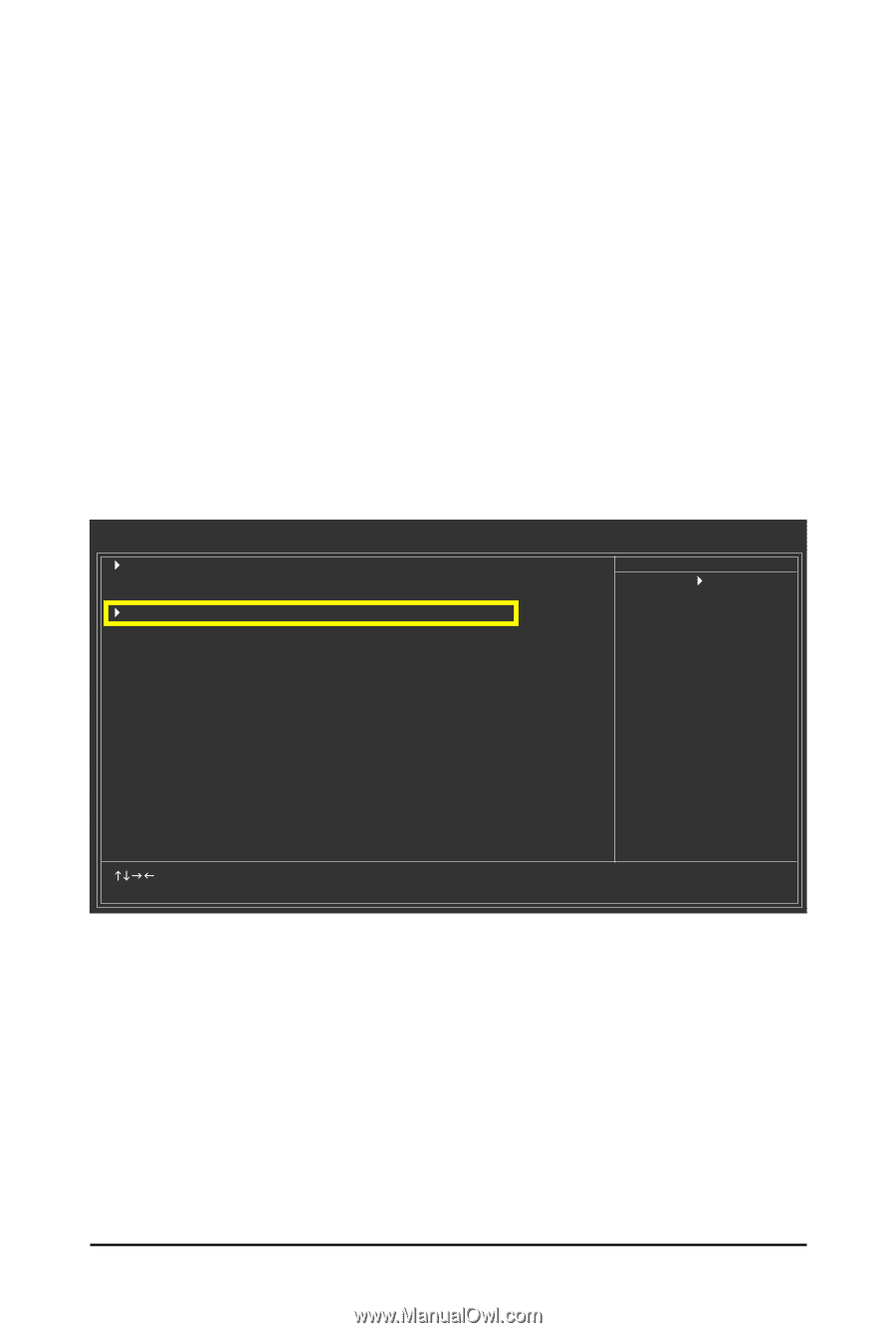
5-1-2 Configuring GIGABYTE SATA2 SATA Controller A. Installing SATA hard drive(s) in your computer Attach one end of the SATA signal cable to the rear of the SATA hard drive and the other end to available SATA port on the motherboard. If there is more than one SATA controller on your motherboard, refer to "Chapter 1," Hardware Installation," to identify the SATA controller for the SATA port. (For example, on this motherboard, the GSATAII_1, GSATAII_2 and eSATA ports are supported by GIGABYTE SATA2.) Then connect the power connector from your power supply to the hard drive. B. Configuring SATA controller mode and device boot order in BIOS Setup Make sure to configure the SATA controller mode correctly in system BIOS Setup and set the device boot order. Step 1: Turn on your computer and press to enter BIOS Setup during the POST. In BIOS Setup, go to Integrated Periperals --> OnBoard PCIE Device (Figure 1). CMOS Setup Utility-Copyright (C) 1984-2007 Award Software Integrated Peripherals ` IDE Configuration OnChip SATA Controller OnChip SATA Type ` OnBoard PCIE Device Onboard Audio Function Onboard 1394 Function OnChip USB Controller USB EHCI Controller USB Keyboard Support USB Mouse Support Legacy USB storage detect Onboard Serial Port 1 Onboard Parallel Port Parallel Port Mode x ECP Mode Use DMA [Press Enter] [Enabled] [Native IDE] [Press Enter] [Auto] [Enabled] [Enabled] [Enabled] [Disabled] [Disabled] [Enabled] [3F8/IRQ4] [378/IRQ7] [SPP] 3 Item Help Menu Level` KLJI: Move Enter: Select F5: Previous Values +/-/PU/PD: Value F10: Save F6: Fail-Safe Defaults Figure 1 ESC: Exit F1: General Help F7: Optimized Defaults - 83 - Appendix
-
 1
1 -
2
-
3
-
4
-
5
-
6
-
7
-
8
-
9
-
10
-
11
-
12
-
13
-
14
-
15
-
16
-
17
-
18
-
19
-
20
-
21
-
22
-
23
-
24
-
25
-
26
-
27
-
28
-
29
-
30
-
31
-
32
-
33
-
34
-
35
-
36
-
37
-
38
-
39
-
40
-
41
-
42
-
43
-
44
-
45
-
46
-
47
-
48
-
49
-
50
-
51
-
52
-
53
-
54
-
55
-
56
-
57
-
58
-
59
-
60
-
61
-
62
-
63
-
64
-
65
-
66
-
67
-
68
-
69
-
70
-
71
-
72
-
73
-
74
-
75
-
76
-
77
-
 78
78 -
 79
79 -
 80
80 -
 81
81 -
 82
82 -
 83
83 -
 84
84 -
 85
85 -
 86
86 -
 87
87 -
 88
88 -
89
-
90
-
91
-
92
-
93
-
94
-
95
-
96
-
97
-
98
-
99
-
100
-
101
-
102
-
103
-
104
-
105
-
106
-
107
-
108
-
109
-
110
-
111
-
112
-
113
-
114
-
115
-
116
 |
 |