Gigabyte GA-MA790GPT-UD3H Manual - Page 44
CHB Add/Cmd drive strength
 |
UPC - 818313008343
View all Gigabyte GA-MA790GPT-UD3H manuals
Add to My Manuals
Save this manual to your list of manuals |
Page 44 highlights
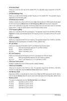
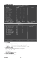
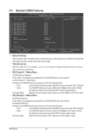
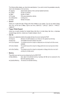
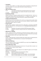
CHB DQS drive strength Options are: Auto (default), 0.75x, 1.0x, 1.25x, 1.5x. CHB Data drive strength Options are: Auto (default), 0.75x, 1.0x, 1.25x, 1.5x. CHB MEMCLK drive strength Options are: Auto (default), 0.75x, 1.0x, 1.25x, 1.5x. CHB Add/Cmd drive strength Options are: Auto (default), 1.0x, 1.25x, 1.5x, 2.0x. CHB CS/ODT drive strength Options are: Auto (default), 1.0x, 1.25x, 1.5x, 2.0x. CHB CKE drive strength Options are: Auto (default), 1.0x, 1.25x, 1.5x, 2.0x. Bank Interleaving Enables or disables memory bank interleaving. Enabled allows the system to simultaneously access different banks of the memory to increase memory performance and stability. (Default: Enabled) Channel interleave Enables or disables memory channel interleaving. Enabled allows the system to simultaneously access different channels of the memory to increase memory performance and stability. (Default: Enabled) ******** System Voltage Optimized ******** System Voltage Control Determines whether to manually set the system voltages. Auto lets the BIOS automatically set the system voltages as required. Manual allows all voltage control items below to be configurable. (Default: Manual) DDR3 Voltage Control Allows you to set memory voltage. Normal Supplies the memory voltage as required. (Default) +0.050V ~ +0.750V Increases memory voltage by 0.050V to 0.750V at 0.05V increment. Note: Increasing memory voltage may result in damage to the memory. NorthBridge Volt Control Allows you to set the North Bridge voltage. Normal Supplies the North Bridge voltage as required. (Default) +0.1V ~ +0.3V Increases North Bridge voltage by 0.1V to 0.3V at 0.1V increment. SouthBridge Volt Control Allows you to set the South Bridge voltage. Normal Supplies the South Bridge voltage as required. (Default) -0.1V ~ +0.2V Increases South Bridge voltage by -0.1V to 0.2V at 0.1V increment. SidePort Mem Volt Control Allows you to set the SidePort memory voltage. Normal Supplies the SidePort memory voltage as required. (Default) +0.1V ~ +0.3V Increases SidePort memory voltage by 0.1V to 0.3V at 0.1V increment. BIOS Setup - 44 -
-
 1
1 -
2
-
3
-
4
-
5
-
6
-
7
-
8
-
9
-
10
-
11
-
12
-
13
-
14
-
15
-
16
-
17
-
18
-
19
-
20
-
21
-
22
-
23
-
24
-
25
-
26
-
27
-
28
-
29
-
30
-
31
-
32
-
33
-
34
-
35
-
36
-
37
-
38
-
 39
39 -
 40
40 -
 41
41 -
 42
42 -
 43
43 -
 44
44 -
 45
45 -
 46
46 -
 47
47 -
 48
48 -
 49
49 -
50
-
51
-
52
-
53
-
54
-
55
-
56
-
57
-
58
-
59
-
60
-
61
-
62
-
63
-
64
-
65
-
66
-
67
-
68
-
69
-
70
-
71
-
72
-
73
-
74
-
75
-
76
-
77
-
78
-
79
-
80
-
81
-
82
-
83
-
84
-
85
-
86
-
87
-
88
-
89
-
90
-
91
-
92
-
93
-
94
-
95
-
96
-
97
-
98
-
99
-
100
-
101
-
102
-
103
-
104
 |
 |