Gigabyte GA-N650SLI-DS4 Manual - Page 17
Setup of an SLI Scalable Link Interface Configuration - performance
 |
UPC - 818313003348
View all Gigabyte GA-N650SLI-DS4 manuals
Add to My Manuals
Save this manual to your list of manuals |
Page 17 highlights
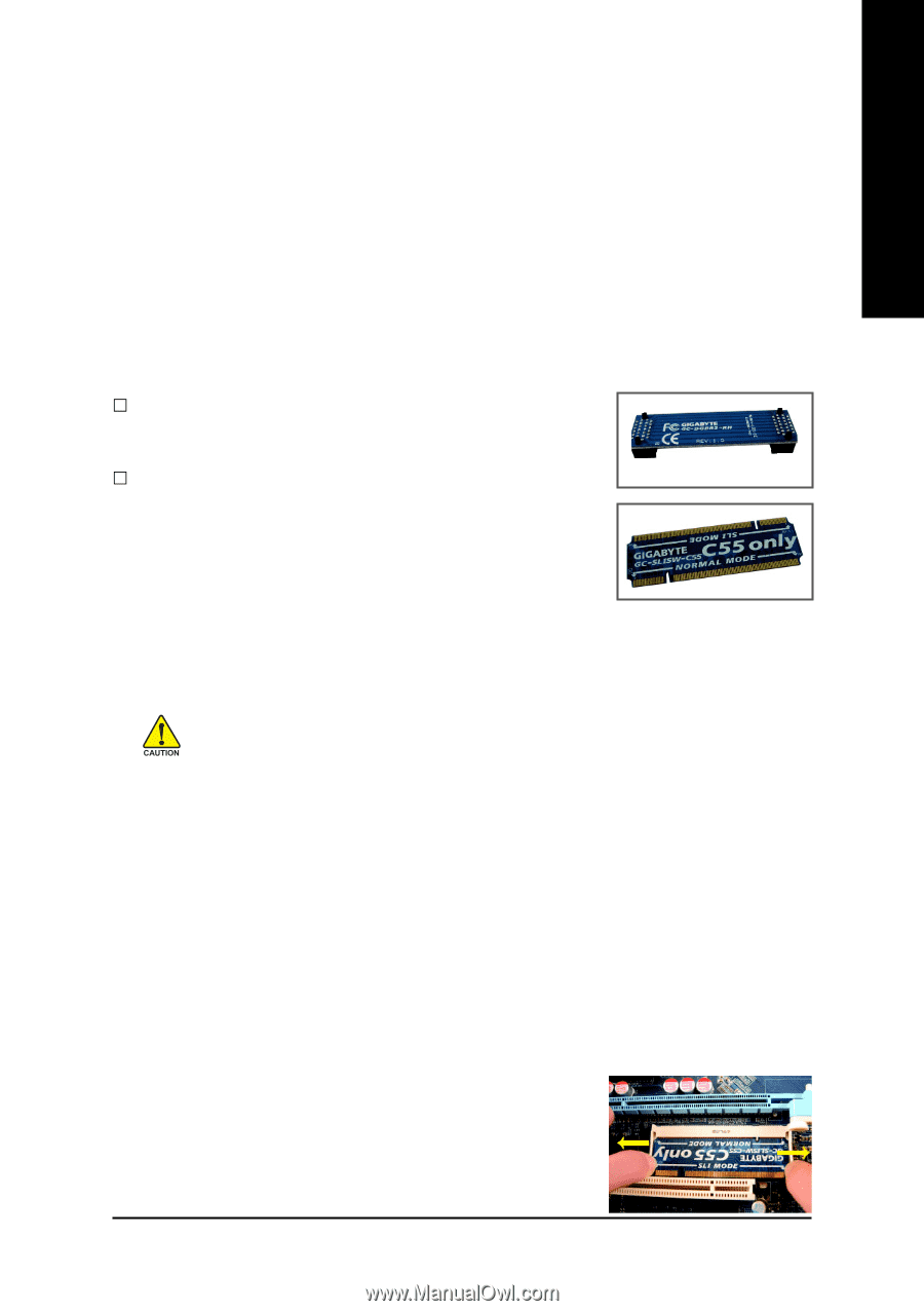
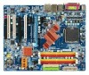
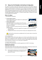
English 1-6 Setup of an SLI (Scalable Link Interface) Configuration The nVIDIA® nForce 650i SLI chipset offers blistering graphics performance with the ability to bridge two nVIDIA® SLI-ready PCI ExpressTM graphics cards! The SLI design takes advantage of the increased bandwidth of the PCI ExpressTM bus architecture, features hardware and software innovations within nVIDIA® GPU (graphics processing unit) and the nVIDIA® nForce 650i SLI chipset. Together, the nVIDIA® SLI technologies work seamlessly to allow two graphics cards to operate in parallel and share the work and deliver heart-pounding PC performance. This section introduces steps to configure an SLI system on the GA-N650SLI-DS4 motherboard. Before You Begin-- I. Understanding the components: … The SLI bridge connector The SLI bridge connector is used to bridge two SLI-capable graphics cards to enable SLI operation. … The SLI switch module SLI Bridge Connector Normal Mode (default): In Normal Mode, the first PCIe x16 slot (PCIE_16_1) operates at up to x16, whereas the second PCIe x16 slot becomes unavailable. SLI Mode: In SLI Mode, you may use the two PCIe x16 slots for the following functions: SLI Switch Module 1. SLI Configuration: Install two SLI-capable PCIe x16 graphics cards of the same model to enable SLI function. 2. Independent PCI x8 slots: Use the two PCIe x16 slots as two independent PCIe x8 slots. Both of the PCIe x16 slots will be unavailable when the SLI switch module is removed from the motherboard. II. Power Requirements: Before installation, assure that the power supply you use is able to provide sufficient power to fully support an SLI configuration and other components in your system. We recommend a power supply that provides at least 20A 5V and 12V current and a minimum of 400W wattage. Note that the exact power requirements will depend on your overall system configurations. III. Supported Operating Systems: Only Windows XP operating system is currently supported by the nVIDIA® SLI technology. Enabling SLI Operation Setting the SLI switch module: The SLI switch module is set to Normal Mode operation by factory default, so the first step is to take out the module from the socket, turn it around and insert it in the SLI Mode direction. Step 1: Gently spread the retaining clips of the socket and the module will be released. Hold the module by the edges and lift it away from the socket. - 17 - Hardware Installation
-
 1
1 -
2
-
3
-
4
-
5
-
6
-
7
-
8
-
9
-
10
-
11
-
 12
12 -
 13
13 -
 14
14 -
 15
15 -
 16
16 -
 17
17 -
 18
18 -
 19
19 -
 20
20 -
 21
21 -
 22
22 -
23
-
24
-
25
-
26
-
27
-
28
-
29
-
30
-
31
-
32
-
33
-
34
-
35
-
36
-
37
-
38
-
39
-
40
-
41
-
42
-
43
-
44
-
45
-
46
-
47
-
48
-
49
-
50
-
51
-
52
-
53
-
54
-
55
-
56
-
57
-
58
-
59
-
60
-
61
-
62
-
63
-
64
-
65
-
66
-
67
-
68
-
69
-
70
-
71
-
72
-
73
-
74
-
75
-
76
-
77
-
78
-
79
-
80
-
81
-
82
-
83
-
84
-
85
-
86
-
87
-
88
 |
 |