Gigabyte GA-N650SLI-DS4L Manual
Gigabyte GA-N650SLI-DS4L Manual
 |
View all Gigabyte GA-N650SLI-DS4L manuals
Add to My Manuals
Save this manual to your list of manuals |
Gigabyte GA-N650SLI-DS4L manual content summary:
- Gigabyte GA-N650SLI-DS4L | Manual - Page 1
GA-N650SLI-DS4L LGA775 socket motherboard for Intel® CoreTM processor family/ Intel® Pentium® processor family/Intel® Celeron® processor family User's Manual Rev. 1001 12ME-N650DS4L-1001R - Gigabyte GA-N650SLI-DS4L | Manual - Page 2
Motherboard GA-N650SLI-DS4L Oct. 15, 2007 Motherboard GA-N650SLI-DS4L Oct. 15, 2007 - Gigabyte GA-N650SLI-DS4L | Manual - Page 3
with the product. „ For detailed product information, carefully read the User's Manual. „ For instructions on how to use GIGABYTE's unique features, read or download the information on/from the Support\Motherboard\Technology Guide page on our website. For product-related information, check on our - Gigabyte GA-N650SLI-DS4L | Manual - Page 4
Box Contents ...6 OptionalItems ...6 GA-N650SLI-DS4L Motherboard Layout 7 Block Diagram ...8 Chapter 1 Hardware Installation 9 1-1 Installation Precautions 9 1-2 Product Specifications 10 1-3 Installing the CPU and CPU Cooler 13 1-3-1 Installing the CPU 13 1-3-2 Installing the CPU Cooler 15 - Gigabyte GA-N650SLI-DS4L | Manual - Page 5
Driver CD Information 60 3-4 Hardware Information 61 3-5 Contact Us ...61 Chapter 4 Unique Features 63 4-1 Xpress Recovery2 63 4-2 BIOS Update Utilities 68 4-2-1 Updating the BIOS with the Q-Flash Utility 68 4-2-2 Updating the BIOS with the @BIOS Utility 71 4-3 EasyTune 5 ...73 4-4 Windows - Gigabyte GA-N650SLI-DS4L | Manual - Page 6
Box Contents GA-N650SLI-DS4L motherboard Motherboard driver disk Motherboard driver disk (For Windows Vista) User's Manual Quick Installation Guide Intel® LGA775 CPU Installation Guide One IDE cable and one floppy disk drive cable Two SATA 3Gb/s cables I/O Shield SLI Bridge Retention Bracket • The - Gigabyte GA-N650SLI-DS4L | Manual - Page 7
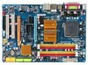
GA-N650SLI-DS4L Motherboard Layout KB_MS COAXIAL OPTICAL LGA775 CPU_FAN PWR_FAN ATX COMA LPT ATX_12V R_USB LAN USB AUDIO PCIE_1 F_AUDIO nVIDIA® nForce 650i SLI RTL8211B PCIE_16_1 NB_FAN PCIE_2 NV_SLI6 JP1 NV_SLI4 NV_SLI5 NV_SLI3 CODEC NV_SLI1 NV_SLI2 PCIE_16_2 GA-N650SLI-DS4L - Gigabyte GA-N650SLI-DS4L | Manual - Page 8
CPU CLK+/- (333/266/200/133 MHz) Host Interface DDR2 800/667/533 MHz Normal Mode SLI Mode Switch PCI Express x 16 Bus PCI Express Bus nVIDIA® nForce 650i SLI Northbridge Dual Channel Memory x1 x1 PCIe CLK (100 MHz) 2 PCI Express x 1 PCI Bus LAN RJ45 RTL 8211B nVIDIA® nForce 650i SLI - Gigabyte GA-N650SLI-DS4L | Manual - Page 9
manual and follow these procedures: • Prior to installation, do not remove or break motherboard S/N (ESD) wrist strap when handling electronic components such as a motherboard, CPU or memory. If you do not have an ESD wrist steps or have a problem related to the use of the product, please consult - Gigabyte GA-N650SLI-DS4L | Manual - Page 10
® Celeron® processor in the LGA 775 package (Go to GIGABYTE's website for the latest CPU support list.) Š L2 cache varies with CPU Š 1333/1066/800/533 MHz FSB Š North Bridge: nVIDIA® nForce 650i SLI Š South Bridge: nVIDIA® nForce 650i SLI Š 4 x 1.8V DDR2 DIMM sockets supporting up to 8 GB of system - Gigabyte GA-N650SLI-DS4L | Manual - Page 11
ATX main power connector Š 1 x 4-pin ATX 12V power connector Š 1 x floppy disk drive connector Š 1 x IDE connector Š 4 x SATA 3Gb/s connectors Š 1 x CPU fan header Š 1 x system fan header Š 1 x power fan header Š 1 x North Bridge fan header Š 1 x front panel header Š 1 x front panel audio - Gigabyte GA-N650SLI-DS4L | Manual - Page 12
2V Š Frequency adjustments in BIOS Setup (CPU/Memory/PCIe) allow you to: - Adjust CPU host frequency from 100 MHz to 650 MHz with 1 MHz increment - Adjust Memory frequency - Adjust PCI Express x16 frequency from 100 MHz to 150 MHz with 1 MHz increment Š Support for Microsoft® Windows® Vista/XP/2000 - Gigabyte GA-N650SLI-DS4L | Manual - Page 13
so according to your hardware specifications including the CPU, graphics card, memory, hard drive, etc. 1-3-1 Installing the CPU A. Locate the alignment keys on the motherboard CPU socket and the notches on the CPU. LGA775 CPU Socket Alignment Key LGA 775 CPU Alignment Key Pin One Corner of the - Gigabyte GA-N650SLI-DS4L | Manual - Page 14
one corner of the CPU socket (or you may align the CPU notches with the socket alignment keys) and gently insert the CPU into position. Step 5: Once the CPU is properly inserted, replace the load plate and push the CPU socket lever back into its locked position. GA-N650SLI-DS4L Motherboard - 14 - - Gigabyte GA-N650SLI-DS4L | Manual - Page 15
. Check that the Male and Female push pins are joined closely. (Refer to your CPU cooler installation manual for instructions on installing the cooler.) Step 5: After the installation, check the back of the motherboard. If the push pin is inserted as the picture above, the installation is complete - Gigabyte GA-N650SLI-DS4L | Manual - Page 16
sure that the motherboard supports the memory. It is recommended that memory of the same capacity, brand, speed, and chips be used. (Go to GIGABYTE's website for the latest memory support list.) • Always in the same colored DDR2 sockets for optimum performance. GA-N650SLI-DS4L Motherboard - 16 - - Gigabyte GA-N650SLI-DS4L | Manual - Page 17
power outlet to prevent damage to the memory module. DDR2 DIMMs are not compatible to DDR DIMMs. Be sure to install DDR2 DIMMs on this motherboard. Notch DDR2 DIMM A DDR2 memory module has a notch, so it can only fit in one direction. Follow the steps below to correctly install your memory - Gigabyte GA-N650SLI-DS4L | Manual - Page 18
an expansion card: • Make sure the motherboard supports the expansion card. Carefully read the manual that came with your expansion card. • from the slot. GA-N650SLI-DS4L Motherboard - 18 - • Removing the Card from the PCIE_16_2 Slot: Press the white latch at the end of the PCI Express x16 slot to - Gigabyte GA-N650SLI-DS4L | Manual - Page 19
(Scalable Link Interface) Configuration The nVIDIA® nForce 650i SLI chipset offers blistering graphics performance with the ability to bridge two NVIDIA SLI-ready PCI ExpressTM graphics cards! This section provides instructions on configuring an SLI system. A. Before You Begin 1. Understanding the - Gigabyte GA-N650SLI-DS4L | Manual - Page 20
in the SLI gold edge connectors on top of both cards. Make sure the two mini female slots on the bridge connector securely fit onto the SLI gold edge connetors of both cards. Female slots on the bridge connector Gold edge connector on the top of the graphics card GA-N650SLI-DS4L Motherboard - 20 - Gigabyte GA-N650SLI-DS4L | Manual - Page 21
retention bracket included with the motherboard and secure the retention bracket SLI configuration screen. Ensure SLI mode is enabled. (The SLI configuration screen may differ by driver version.) (Note) Procedure for enabling SLI technology may slightly differ by graphics cards. Refer to the manual - Gigabyte GA-N650SLI-DS4L | Manual - Page 22
USB Port The USB port supports the USB 2.0/1.1 specification. 1 Gbps data rate. The following describes motherboard. • When removing the cable, pull it straight out from the connector. Do not rock it side to side to prevent an electrical short inside the cable connector. GA-N650SLI-DS4L Motherboard - Gigabyte GA-N650SLI-DS4L | Manual - Page 23
to perform different functions via the audio software. Only microphones still MUST be connected to the default Mic in jack ( ). Refer to the instructions on setting up a 2/4/5.1/ 7.1-channel audio configuration in Chapter 5, "Configuring 2/4/5.1/7.1-Channel Audio." - 23 - Hardware Installation - Gigabyte GA-N650SLI-DS4L | Manual - Page 24
devices. • After installing the device and before turning on the computer, make sure the device cable has been securely attached to the connector on the motherboard. GA-N650SLI-DS4L Motherboard - 24 - - Gigabyte GA-N650SLI-DS4L | Manual - Page 25
supply can supply enough stable power to all the components on the motherboard. Before connecting the power connector, first make sure the power supply the correct orientation. The 12V power connector mainly supplies power to the CPU. If the 12V power connector is not connected, the computer will - Gigabyte GA-N650SLI-DS4L | Manual - Page 26
the fan headers to prevent your CPU, North Bridge and system from overheating. Overheating may result in damage to the CPU/North Bridge or the system may hang. • These fan headers are not configuration jumper blocks. Do not place a jumper cap on the headers. GA-N650SLI-DS4L Motherboard - 26 - - Gigabyte GA-N650SLI-DS4L | Manual - Page 27
stripe of different color. 33 1 34 2 8) IDE1 (IDE Connector) The IDE connector supports up to two IDE devices such as hard drives and optical drives. Before attaching the IDE the IDE devices, read the instructions from the device manufacturers.) 1 2 39 40 - 27 - Hardware Installation - Gigabyte GA-N650SLI-DS4L | Manual - Page 28
connector supports a single SATA device. The nVIDIA® nForce 650i SLI controller supports RAID 0, RAID 1, RAID 5 and RAID 0+1. Refer to Chapter 5, "Configuring SATA Hard Drive(s)," for instructions on and the total number of hard drives must be an even number. GA-N650SLI-DS4L Motherboard - 28 - - Gigabyte GA-N650SLI-DS4L | Manual - Page 29
- 3 MPD- System Status LED S0 On S1 Blinking S3/S4/S5 Off 11) BAT (Battery) The battery provides power to keep the values (such as BIOS configurations, date, and time information) in the CMOS when the computer is turned off. Replace the battery when the battery voltage drops to a low level - Gigabyte GA-N650SLI-DS4L | Manual - Page 30
heard if no problem is detected at system startup. If a problem is detected, the BIOS may issue beeps in different patterns to indicate the problem. Refer to Chapter 5, "Troubleshooting," for information about and the pin assignments are matched correctly. GA-N650SLI-DS4L Motherboard - 30 - - Gigabyte GA-N650SLI-DS4L | Manual - Page 31
the pin assignments of the motherboard header. Incorrect connection between the module connector and the motherboard header will make the device unable panel audio header supports HD audio by default. If your chassis provides an AC'97 front panel audio module, refer to the instructions on how to - Gigabyte GA-N650SLI-DS4L | Manual - Page 32
header supports digital S/PDIF in and can connect to an audio device that supports digital audio out via an optional S/PDIF in cable. For purchasing the optional S/PDIF in cable, please contact the local dealer. Pin No. Definition 1 1 Power 2 SPDIFI 3 GND GA-N650SLI-DS4L Motherboard - 32 - Gigabyte GA-N650SLI-DS4L | Manual - Page 33
and unplug the power cord from the power outlet to prevent damage to the USB bracket. 18) CI1 (Chassis Intrusion Header) This motherboard provides a chassis detection feature that detects if the chassis cover has been removed. This function requires a chassis with chassis intrusion detection design - Gigabyte GA-N650SLI-DS4L | Manual - Page 34
jumper. Failure to do so may cause damage to the motherboard. • After system restart, go to BIOS Setup to load factory defaults (select Load Optimized Defaults) or manually configure the BIOS settings (refer to Chapter 2, "BIOS Setup," for BIOS configurations). GA-N650SLI-DS4L Motherboard - 34 - - Gigabyte GA-N650SLI-DS4L | Manual - Page 35
the GIGABYTE Q-Flash or @BIOS utility. • Q-Flash allows the user to quickly and easily upgrade or back up BIOS without entering the operating system. • @BIOS is a Windows-based utility that searches and downloads the latest version of BIOS from the Internet and updates the BIOS. For instructions on - Gigabyte GA-N650SLI-DS4L | Manual - Page 36
F12>: Boot Menu : Qflash B. The POST Screen Function Keys Motherboard Model BIOS Version Award Modular BIOS v6.00PG, An Energy Star Ally Copyright (C) 1984-2007, Award Software, Inc. GA-N650SLI-DS4L D1 . . . . : BIOS Setup/Q-Flash : XpressRecovery2 : Boot Menu : Qflash 09 - Gigabyte GA-N650SLI-DS4L | Manual - Page 37
Version: D1) CMOS Setup Utility-Copyright (C) 1984-2007 Award Software ` Standard CMOS Features ` Advanced BIOS Features ` Integrated Peripherals ` Power Management Setup ` PnP/PCI Configurations ` PC Health Status ` MB Intelligent Tweaker(M.I.T.) Load Fail-Safe Defaults Load Optimized Defaults - Gigabyte GA-N650SLI-DS4L | Manual - Page 38
and exit BIOS Setup. (Pressing can also carry out this task.) „ Exit Without Saving Abandon all changes and the previous settings remain in effect. Pressing to the confirmation message will exit BIOS Setup. (Pressing can also carry out this task.) GA-N650SLI-DS4L Motherboard - 38 - Gigabyte GA-N650SLI-DS4L | Manual - Page 39
None] [None] [None] Drive A Floppy 3 Mode Support [1.44M, 3.5"] [Disabled] Halt On [All, But the three methods below: • Auto Lets BIOS automatically detect IDE/SATA devices during the POST Manual skip the detection of the device during the POST for faster system startup. Allows you to manually - Gigabyte GA-N650SLI-DS4L | Manual - Page 40
parameters manually, /3.5", 2.88M/3.5". Floppy 3 Mode Support Allows you to specify whether the BIOS POST. Base Memory Also called conventional memory. Typically, 640 KB will be reserved for the MS-DOS operating system. Extended Memory The amount of extended memory. GA-N650SLI-DS4L Motherboard - Gigabyte GA-N650SLI-DS4L | Manual - Page 41
Enabled Enables all CPU cores and multi-threading capability. (Default) Disabled Enables only one CPU core. (Note) This item is present only if you install a CPU that supports this feature. For more information about Intel CPUs' unique features, please visit Intel's website. - 41 - BIOS Setup - Gigabyte GA-N650SLI-DS4L | Manual - Page 42
display the GIGABYTE Logo at PCI Express graphics card on the PCIE_16_2 slot as the first display. (Note) This item is present only if you install a CPU that supports this feature. For more information about Intel CPUs' unique features, please visit Intel's website. GA-N650SLI-DS4L Motherboard - Gigabyte GA-N650SLI-DS4L | Manual - Page 43
Onboard LAN Boot ROM NV Serial-ATA Controller IDE Prefetch Mode On-Chip USB USB Keyboard Support USB Mouse Support Onboard Audio Function ` SMART LAN Legacy USB storage detect Onboard Serial Port 1 Onboard channel of the second integrated SATA 3Gb/s controller. (Default: Enabled) - 43 - BIOS Setup - Gigabyte GA-N650SLI-DS4L | Manual - Page 44
function. (Default: Auto) If you wish to install a 3rd party add-in audio card instead of using the onboard audio, set this item to Disabled. GA-N650SLI-DS4L Motherboard - 44 - - Gigabyte GA-N650SLI-DS4L | Manual - Page 45
LAN Cable Is Attached... If no LAN cable is attached to the motherboard, the Status fields of all four pairs of wires will show Open of 10/100/1000Mbps in Windows mode or when the LAN Boot ROM is activated. When a Cable Problem Occurs... If a cable problem occurs on a specified pair - BIOS Setup - Gigabyte GA-N650SLI-DS4L | Manual - Page 46
LPT port in ECP mode. This item is configurable only if Parallel Port Mode is set to ECP or ECP+EPP mode. Options are: 3 (default), 1. GA-N650SLI-DS4L Motherboard - 46 - - Gigabyte GA-N650SLI-DS4L | Manual - Page 47
Alarm x Time (hh:mm:ss) Alarm HPET Support (Note) Power On By Mouse Power On By to enter the ACPI S3 (Suspend to RAM) sleep state. In S3 sleep state by a wake-up signal from a PCI or PCIe device. Note: To use a wake-up signal from a modem that supports wake-up function. (Default: Enabled) USB - Gigabyte GA-N650SLI-DS4L | Manual - Page 48
power, or the settings may not be effective. HPET Support (Note) Enables or disables High Precision Event Timer (HPET) for Windows® Vista® operating system. (Default: Enabled) Power On the AC power. (Note) Supported on Windows® Vista® operating system only. GA-N650SLI-DS4L Motherboard - 48 - - Gigabyte GA-N650SLI-DS4L | Manual - Page 49
F6: Fail-Safe Defaults ESC: Exit F1: General Help F7: Optimized Defaults BIOS auto-assigns IRQ to the first PCI slot. (Default) Assigns IRQ 3,4,5,7,9,10,11,12,14,15 to the first PCI slot. BIOS auto-assigns IRQ to the second PCI slot. (Default) Assigns IRQ 3,4,5,7,9,10,11,12,14,15 to the second - Gigabyte GA-N650SLI-DS4L | Manual - Page 50
), 60oC/140oF, 70oC/158oF, 80oC/ 176oF, 90oC/194oF. CPU/SYSTEM/POWER FAN Fail Warning Allows the system to emit warning sound if the CPU/system/power fan is not connected or fails. Check the fan condition or fan connection when this occurs. (Default: Disabled) GA-N650SLI-DS4L Motherboard - 50 - - Gigabyte GA-N650SLI-DS4L | Manual - Page 51
Smart FAN Control is set to Enabled. Auto Lets BIOS autodetect the type of CPU fan installed and sets the optimal CPU fan control mode. (Default) Voltage Sets Voltage mode for a 3-pin CPU fan. PWM Sets PWM mode for a 4-pin CPU fan. System Smart FAN Control Enables or disables the system - Gigabyte GA-N650SLI-DS4L | Manual - Page 52
PCIe Bus, Slot 1, MHz [100] KLJI: Move Enter: Select F5: Previous Values +/-/PU/PD: Value F10: Save F6: Fail-Safe Defaults ESC: Exit F1: General Help F7: Optimized Defaults (Note) This item is present only if you install a CPU that supports this feature. GA-N650SLI-DS4L Motherboard - 52 - - Gigabyte GA-N650SLI-DS4L | Manual - Page 53
. The adjustable range is from 100 MHz to 650 MHz. For a 533 MHz FSB CPU, set this item to 133 MHz. For an 800 MHz FSB CPU, set this item to 200 MHz. For a 1066 MHz FSB CPU, set this item to 266 MHz. For a 1333 MHz FSB CPU, set this item to 333 MHz. Important It is highly recommended that - Gigabyte GA-N650SLI-DS4L | Manual - Page 54
as required. The adjustable range is dependent on the CPU being installed. (Default: Normal) Note: Increasing CPU voltage may result in damage to your CPU or reduce the useful life of the CPU. Normal CPU Vcore Displays the normal operating voltage of your CPU. GA-N650SLI-DS4L Motherboard - 54 - - Gigabyte GA-N650SLI-DS4L | Manual - Page 55
stable BIOS settings for the motherboard. BIOS Load Optimized Defaults Press on this item and then press the key to load the optimal BIOS default settings. The BIOS defaults settings helps the system to operate in optimum state. Always load the Optimized defaults after updating the BIOS - Gigabyte GA-N650SLI-DS4L | Manual - Page 56
you to view the BIOS settings but not to make changes. To clear the password, press on the password item and when requested for the password, press again. The message "PASSWORD DISABLED" will appear, indicating the password has been cancelled. GA-N650SLI-DS4L Motherboard - 56 - - Gigabyte GA-N650SLI-DS4L | Manual - Page 57
Save to CMOS and EXIT (SYe/tNU)?seYr Password ` PnP/PCI Configurations Save & Exit Setup ` PC Health Status Exit Without Saving Flash KLJI: Select Item F10: Save & Exit Setup F11: Save CMOS to BIOS F12: Load CMOS from BIOS Save Data to CMOS Press on this item and press the key - Gigabyte GA-N650SLI-DS4L | Manual - Page 58
GA-N650SLI-DS4L Motherboard - 58 - - Gigabyte GA-N650SLI-DS4L | Manual - Page 59
other drivers. • After the drivers are installed, follow the onscreen instructions to restart your system. You can install other applications included in the motherboard driver disk. • For USB 2.0 driver support under the Windows XP operating system, please install the Windows XP Service Pack - Gigabyte GA-N650SLI-DS4L | Manual - Page 60
all the tools and applications that GIGABYTE develops and some free software. You may press the Install button following an item to install it. 3-3 Driver CD Information This page provides information about the drivers, applications and tools in this driver disk. GA-N650SLI-DS4L Motherboard - 60 - - Gigabyte GA-N650SLI-DS4L | Manual - Page 61
3-4 Hardware Information This page provides information about the hardware devices on this motherboard. 3-5 Contact Us Check the contacts information of the GIGABYTE headquarter in Taiwan and the overseas branch offices on the last page of this manual. - 61 - Drivers Installation - Gigabyte GA-N650SLI-DS4L | Manual - Page 62
GA-N650SLI-DS4L Motherboard - 62 - - Gigabyte GA-N650SLI-DS4L | Manual - Page 63
after the operating system and drivers are installed. • The amount of Windows® XP with SP1 or later • Xpress Recovery and Xpress Recovery2 are different utilities. For example, a backup file created with Xpress Recovery cannot be restored using Xpress Recovery2. • USB hard drives are not supported - Gigabyte GA-N650SLI-DS4L | Manual - Page 64
Windows XP as the example operating system.) A. Installing Windows XP and Partitioning the Hard Drive 1. Set CD-ROM drive as the first boot device under "Advanced BIOS Features" in the BIOS ) and begin the installation of the operating system (Figure 3). Figure 3 GA-N650SLI-DS4L Motherboard - 64 - - Gigabyte GA-N650SLI-DS4L | Manual - Page 65
4. After the operating system is installed, right-click the My Computer icon on your desktop and select Manage (Figure 4). Go to Computer Management to check disk allocation. Xpress Recovery2 will save the backup file to the unallocated space (black stripe along the top)(Figure 5). Please note that - Gigabyte GA-N650SLI-DS4L | Manual - Page 66
operating system. When the Windows operating system is detected, Xpress Recovery2 will begin the backup process (Figure 11). Figure 10 Figure 11 3. When finished, go to Disk Management to check disk allocation. Figure 12 GA-N650SLI-DS4L Motherboard Xpress Recovery2 will automatically create - Gigabyte GA-N650SLI-DS4L | Manual - Page 67
D. Using the Restore Function in Xpress Recovery2 Select RESTORE to restore the backup to your hard drive in case the system breaks down. The RESTORE option will not be present if no backup is created before (Figure 13, 14). Figure 13 Figure 14 E. Removing the Backup 1. If you wish to remove the - Gigabyte GA-N650SLI-DS4L | Manual - Page 68
Windows environment. @BIOS will download the latest BIOS file from the nearest @BIOS server site and update the BIOS. 4-2-1 Updating the BIOS with the Q-Flash Utility A. Before You Begin: 1. From GIGABYTE's website, download the latest compressed BIOS update file that matches your motherboard model - Gigabyte GA-N650SLI-DS4L | Manual - Page 69
Update BIOS from Drive and press . • The Save Main BIOS to Drive option allows you to save the current BIOS file. • Q-Flash only supports BIOS update file and press . Make sure the BIOS update file matches your motherboard model. Step 2: The process of the system reading the BIOS - Gigabyte GA-N650SLI-DS4L | Manual - Page 70
F11: Save CMOS to BIOS F12: Load CMOS from BIOS Load Optimized Defaults Press to load BIOS defaults Step 6: Select Save & Exit Setup and then press to save settings to CMOS and exit BIOS Setup. The procedure is complete after the system restarts. GA-N650SLI-DS4L Motherboard - 70 - - Gigabyte GA-N650SLI-DS4L | Manual - Page 71
and Using @BIOS: Use the motherboard driver disk included with the motherboard to install @BIOS. • Installing the @BIOS utility. • Accessing the @BIOS utility. Click Start>All Programs>GIGABYTE> @BIOS Select @BIOS and click Install. C. Options and Instructions: 1. Save the Current BIOS File In - Gigabyte GA-N650SLI-DS4L | Manual - Page 72
in an unbootable system. • If the BIOS update file for your motherboard is not present on the @BIOS server site, please manually download the BIOS update file from GIGABYTE's website and follow the instructions in "Update the BIOS without Using the Internet Update Function" below. Step 4: As the - Gigabyte GA-N650SLI-DS4L | Manual - Page 73
the BIOS Setup program. EasyTune 5 provides the following functions : (Note 1) overclocking/overvoltage, C.I.A./ M.I.B. (Note 2), smart fan control, and hardware monitoring and warning. (For instructions on using EasyTune5, read or download the information on/from the Support\Motherboard\Utility - Gigabyte GA-N650SLI-DS4L | Manual - Page 74
ReadyBoost allows you to use flash memory on a Windows Vista certified USB flash drive to boost your computer's performance. You may enable ReadyBoost of memory to use for ReadyBoost acceleration is one to three times the amount of RAM installed in your computer. GA-N650SLI-DS4L Motherboard - 74 - - Gigabyte GA-N650SLI-DS4L | Manual - Page 75
BIOS Setup. C . Configure a RAID array in RAID BIOS. (Note 1) D. Make a floppy disk containing the SATA RAID driver. (Note 2) E. Install the SATA RAID driver • An empty formatted floppy disk. • Windows Vista/XP/2000 setup disk. • Motherboard driver disk. 5-1-1 Configuring the Onboard SATA Controller - Gigabyte GA-N650SLI-DS4L | Manual - Page 76
Support USB Mouse Support BIOS Setup. Figure 2 The BIOS Setup menus described in this section may differ from the exact settings for your motherboard. The actual BIOS Setup menu options you will see shall depend on the motherboard you have and the BIOS version. GA-N650SLI-DS4L Motherboard - Gigabyte GA-N650SLI-DS4L | Manual - Page 77
BIOS Enter the RAID BIOS setup utility to configure a RAID array. For a non-RAID configuration, please skip this step and proceed to the installation of Windows operating system. Step 1: After the POST memory test mode. The supported RAID modes is selected, you can manually set the striping block - Gigabyte GA-N650SLI-DS4L | Manual - Page 78
] NdaO1ta.0?.M ST3120026AS [J] Add 1.1.M ST3120026AS [Y] YES [N] NO [I] Del Capacity 111.79GB 111.79GB [ESC] Quit [F6] Back [F7] Finish [TAB] Navigate [KL] Select [ENTER] Popup Figure 6 GA-N650SLI-DS4L Motherboard - 78 - - Gigabyte GA-N650SLI-DS4L | Manual - Page 79
utility, press in the main menu or + in the Array List screen. Now, you can proceed to the installation of the SATA controller driver and operating system. - 79 - Appendix - Gigabyte GA-N650SLI-DS4L | Manual - Page 80
drivers are for the nVIDIA® nForce 650i SLI chipset. For example, to install Windows motherboard driver disk. From your optical drive folder, double click the MENU.exe file in the BootDrv folder (Figure 3). A command prompt window will open similar to that in Figure 2. GA-N650SLI-DS4L Motherboard - Gigabyte GA-N650SLI-DS4L | Manual - Page 81
floppy disk containing the SATA RAID driver and press (Figure 2). Windows Setup Setup could not determine the type of one or more mass storage devices installed in your system, or you have chosen to manually specify an adapter. Currently, Setup will load support for the following mass storage - Gigabyte GA-N650SLI-DS4L | Manual - Page 82
use with Windows, press ENTER. S=Specify Additional Device Enter=Continue F3=Exit Figure 4 If a message appears saying one or some file(s) cannot be found, please check the floppy disk or copy the correct SATA RAID driver again from the motherboard driver disk. GA-N650SLI-DS4L Motherboard - 82 - Gigabyte GA-N650SLI-DS4L | Manual - Page 83
, press to continue the driver installation from the floppy disk. The driver installation will be finished in about one minute. Windows Setup Setup will load support for the following mass storage device(s): NVIDIA RAID CLASS Driver (required) NVIDIA nForce Storage Controller (required) * To - Gigabyte GA-N650SLI-DS4L | Manual - Page 84
support 44.1KHz/ 48KHz/ 96KHz/192KHz sampling rate. instructions use Windows XP as the example operating system.) Step 1: After installing the audio driver motherboard driver disk and your operating system has been updated with the latest Service Pack for Windows GA-N650SLI-DS4L Motherboard - 84 - - Gigabyte GA-N650SLI-DS4L | Manual - Page 85
Step 2: Click the Audio I/O tab. In the speaker list on the left, select 2CH Speaker, 4CH Speaker, 6CH Speaker, or 8CH Speaker according to the type of speaker configuration you wish to set up. Step 3: Everytime you connect an audio device to an audio jack, the Connected device box appears. Select - Gigabyte GA-N650SLI-DS4L | Manual - Page 86
for audio processing. A. Installing the S/PDIF In Cable: Step 1: First, attach the connector at the end of the cable to the SPDIF_IN header on your motherboard. Step 2: Secure the metal bracket to the chassis back panel with a screw. GA-N650SLI-DS4L Motherboard - 86 - - Gigabyte GA-N650SLI-DS4L | Manual - Page 87
Optical Cable C. Configuring S/PDIF out: Click the tool icon in the DIGITAL section. In the S/PDIF In/Out Settings dialog box, select an output sampling rate and select (or disable) the output source. Click OK to complete the configuration. - 87 - Appendix - Gigabyte GA-N650SLI-DS4L | Manual - Page 88
5-2-3 Configuring Microphone Recording Step 1: After installing the audio driver, the Audio Manager icon will appear in your system tray. Double-click the icon to access the Locate the Volume icon in your system tray and click it to open the volume control panel. GA-N650SLI-DS4L Motherboard - 88 - - Gigabyte GA-N650SLI-DS4L | Manual - Page 89
Step 4: To hear the sound being recorded during the record- ing process when using the microphone function on or the front panel, do not select the Mute check box under Front Pink In or Front Green In in Master Volume. It is recommended that you set the volume at a middle level. To hear the - Gigabyte GA-N650SLI-DS4L | Manual - Page 90
the Stop button . 5. You may use the Fast Forward button to move to the beginning of a file or the Fast Backward button to the end. GA-N650SLI-DS4L Motherboard - 90 - - Gigabyte GA-N650SLI-DS4L | Manual - Page 91
5-3 Troubleshooting 5-3-1 Frequently Asked Questions To read more FAQs for your motherboard, please go to the Support\Motherboard\FAQ page on GIGABYTE's website. Q: In the BIOS Setup program, why are some BIOS options missing? A: Some advanced options are hidden in the BIOS Setup program. Press < - Gigabyte GA-N650SLI-DS4L | Manual - Page 92
insert the memory into the memory socket. The problem is verified and solved. Press to enter BIOS Setup. Select "Load Fail-Safe Defaults" (or "Load Optimized Defaults"). Select "Save & Exit Setup" to save changes and exit BIOS Setup. A (Continued...) GA-N650SLI-DS4L Motherboard - 92 - - Gigabyte GA-N650SLI-DS4L | Manual - Page 93
is verified and solved. END If the procedure above is unable to solve your problem, contact the place of purchase or local dealer for help. Or go to the Support\Technical Service Zone page to submit your question. Our customer service staff will reply you as soon as possible. - 93 - Appendix - Gigabyte GA-N650SLI-DS4L | Manual - Page 94
product. Restriction of Hazardous Substances (RoHS) Directive Statement GIGABYTE products have not intended to add and safe from office, your household waste disposal service or where you purchased the manual and we will be glad to help you with your effort. GA-N650SLI-DS4L Motherboard - 94 - - Gigabyte GA-N650SLI-DS4L | Manual - Page 95
Finally, we suggest that you practice other environmentally friendly actions by understanding and using the energy-saving features of this product (where applicable), recycling the inner and outer packaging (including shipping containers) this product was delivered in, and by disposing of or - Gigabyte GA-N650SLI-DS4L | Manual - Page 96
GA-N650SLI-DS4L Motherboard - 96 - - Gigabyte GA-N650SLI-DS4L | Manual - Page 97
- 97 - Appendix - Gigabyte GA-N650SLI-DS4L | Manual - Page 98
GA-N650SLI-DS4L Motherboard - 98 - - Gigabyte GA-N650SLI-DS4L | Manual - Page 99
(Soporte de habla hispano) FAX: +1-626-854-9339 Correo: [email protected] Tech. Support: http://rma.gigabyte-usa.com Web address: http://www.gigabyte.com.mx Singapore GIGA-BYTE SINGAPORE PTE. LTD. WEB address : http://www.gigabyte.sg Thailand WEB address : http://th.giga-byte.com Vietnam WEB - Gigabyte GA-N650SLI-DS4L | Manual - Page 100
language in the language list on the top right corner of the website. GIGABYTE Global Service System To submit a technical or non-technical (Sales/ Marketing) question, please link to : http://ggts.gigabyte.com.tw Then select your language to enter the system. GA-N650SLI-DS4L Motherboard - 100 -
-
 1
1 -
 2
2 -
 3
3 -
 4
4 -
 5
5 -
 6
6 -
 7
7 -
8
-
9
-
10
-
11
-
12
-
13
-
14
-
15
-
16
-
17
-
18
-
19
-
20
-
21
-
22
-
23
-
24
-
25
-
26
-
27
-
28
-
29
-
30
-
31
-
32
-
33
-
34
-
35
-
36
-
37
-
38
-
39
-
40
-
41
-
42
-
43
-
44
-
45
-
46
-
47
-
48
-
49
-
50
-
51
-
52
-
53
-
54
-
55
-
56
-
57
-
58
-
59
-
60
-
61
-
62
-
63
-
64
-
65
-
66
-
67
-
68
-
69
-
70
-
71
-
72
-
73
-
74
-
75
-
76
-
77
-
78
-
79
-
80
-
81
-
82
-
83
-
84
-
85
-
86
-
87
-
88
-
89
-
90
-
91
-
92
-
93
-
94
-
95
-
96
-
97
-
98
-
99
-
100
 |
 |

GA-N650SLI-DS4L
LGA775 socket motherboard for Intel
®
Core
TM
processor family/
Intel
®
Pentium
®
processor family/Intel
®
Celeron
®
processor family
User's Manual
Rev. 1001
12ME-N650DS4L-1001R