Gigabyte GA-P55-UD6 Manual - Page 7
GA-P55-UD6 Motherboard Layout - phase led
 |
UPC - 818313008480
View all Gigabyte GA-P55-UD6 manuals
Add to My Manuals
Save this manual to your list of manuals |
Page 7 highlights
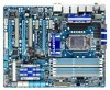
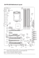
GA-P55-UD6 Motherboard Layout KB_USB R_SPDIF SYS_FAN3 ATX_12V_2X USB_1394_ESATA_2 LGA1156 CPU_FAN PW_SW USB_1394_ESATA_1 USB_LAN2 USB_LAN1 JMB362 F_AUDIO AUDIO PCIEX1_1 (Note 1) RTL8111D PCH_FAN RTL8111D PCIEX1_2 Intel® P55 PCIEX16_1 CODEC CD_IN SPDIF_I PCI1 PCIEX8_1 GA-P55-UD6 BATTERY TPM IC (Note 3) B_BIOS M_BIOS SPDIF_O PCI2 ACPI LED TSB43AB23 DDR3_3 DDR3_2 DDR3_1 DDR3_6 DDR3_5 DDR3_4 MD1 MD2 ATX GD1 GD2 PWR_FAN PHASE LED SYS_FAN1 JMB362 GIGABYTE SATA2 RST_SW IDE SATA2_1 SATA2_0 SATA2_3 SATA2_2 SATA2_5 SATA2_4 GSATA2_1 GSATA2_0 GSATA2_3 GSATA2_2 IT8720 PCIEX4_1 CMOS_SW Debug LED (Note 2) COMA FDD SYS_FAN2 F_USB2 F_1394 F_USB1 F_PANEL (Note 1) Due to a hardware limitation, the PCIEX1_1 slot can only accommodate a shorter PCI Express x1 expansion card. For a longer expansion card, use other expansion slots. (Note 2) For error code information, please refer to Chapter 5. (Note 3) This feature is optional due to different regional policy. - 7 -
-
 1
1 -
 2
2 -
 3
3 -
 4
4 -
 5
5 -
 6
6 -
 7
7 -
 8
8 -
 9
9 -
 10
10 -
 11
11 -
 12
12 -
13
-
14
-
15
-
16
-
17
-
18
-
19
-
20
-
21
-
22
-
23
-
24
-
25
-
26
-
27
-
28
-
29
-
30
-
31
-
32
-
33
-
34
-
35
-
36
-
37
-
38
-
39
-
40
-
41
-
42
-
43
-
44
-
45
-
46
-
47
-
48
-
49
-
50
-
51
-
52
-
53
-
54
-
55
-
56
-
57
-
58
-
59
-
60
-
61
-
62
-
63
-
64
-
65
-
66
-
67
-
68
-
69
-
70
-
71
-
72
-
73
-
74
-
75
-
76
-
77
-
78
-
79
-
80
-
81
-
82
-
83
-
84
-
85
-
86
-
87
-
88
-
89
-
90
-
91
-
92
-
93
-
94
-
95
-
96
-
97
-
98
-
99
-
100
-
101
-
102
-
103
-
104
-
105
-
106
-
107
-
108
-
109
-
110
-
111
-
112
-
113
-
114
-
115
-
116
-
117
-
118
-
119
-
120
-
121
-
122
-
123
-
124
-
125
-
126
-
127
-
128
-
129
-
130
-
131
-
132
-
133
-
134
-
135
-
136
 |
 |
