Gigabyte GA-Z170MX-Gaming 5 User Manual - Page 19
TPM Trusted Platform Module Header, F_USB1/F_USB2 USB 2.0/1.1 Headers, THB_C Thunderbolt
 |
View all Gigabyte GA-Z170MX-Gaming 5 manuals
Add to My Manuals
Save this manual to your list of manuals |
Page 19 highlights
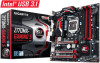
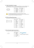
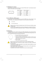
1 23 1 1 23 1 1 23 1 1 23 1 14) F_USB1/F_USB2 (USB 2.0/1.1 Headers) The headers conform to USB 2.0/1.1 specification. Each USB header can provide two USB ports via an Bo_ptional USB bracket. For purchasBinSgSthe optional USB bracket, please contact the local dealer. F_USB30 9 1 10 2 1 Pin No. Definition Pin No. Definition F_ U1 Power (5V) _S 6 USB DY+ F_ 2 Power (5V) 7 GND 3 USB DX- 8 GND _ 4 USB DY- 9 No Pin B S 5 USB DX+ 10 NC 1 23 1 1 23 1 •• Do not plug the IEEE 1394 bracket (2x5-pin) cable into the USB 2.0/1.1 header. •• Prior to installing the USB bracket, 1 23 be sure to turn off your computer and unplug the power cordS B_ from the power outlet to prevent damage to the USB bracket. B S B_ B SS 1 15) TPM (Trusted Platform Module Header) You may connect a TPM (Trusted Platform Module) to this header. _S _S S3 19 1 20 2 B SS S SF Pin No. 1 2 3 4 5 6 7 8 9 10 _ Definition LCLK GND LFRAME NUo Pin LRESET NC LASD3 LAD2 VCC3 LAD1 Pin No. Definition 11 LAD0 12 GNDS 13 NC 14 NC 15 _ _SB3V3 1 23 16 SERIRQ 17 GND 18 NC 19 NC 20 SUSCLK S_ _ B _U _ B F_USB3 F 16) THB_C (Thunderbolt™ Add-in Card Connector) This connector is for a GIGABYTE Thunderbolt™ add-in card. _ _B B_ 1 S3 S_ Pin_No. 1 2 3 4 5 DBefSinSition S GPIOA GPIOB N_-SLP_S3 N_-S4_S5 GND SF U __ 3 Supports a Thunderbolt™ add-in card. _ B_ _ - 19 - _ _B S_
-
 1
1 -
2
-
3
-
4
-
5
-
6
-
7
-
8
-
9
-
10
-
11
-
12
-
13
-
 14
14 -
 15
15 -
 16
16 -
 17
17 -
 18
18 -
 19
19 -
 20
20 -
 21
21 -
 22
22 -
 23
23 -
 24
24 -
25
-
26
-
27
-
28
-
29
-
30
-
31
-
32
-
33
-
34
-
35
-
36
-
37
-
38
-
39
-
40
-
41
-
42
-
43
-
44
 |
 |
