Gigabyte GA-Z170N-Gaming 5 User Manual - Page 15
SATA EXPRESS SATA Express Connector, SATA3 0/1/2/3/4/5 SATA 6Gb/s Connectors, BAT Battery
 |
View all Gigabyte GA-Z170N-Gaming 5 manuals
Add to My Manuals
Save this manual to your list of manuals |
Page 15 highlights
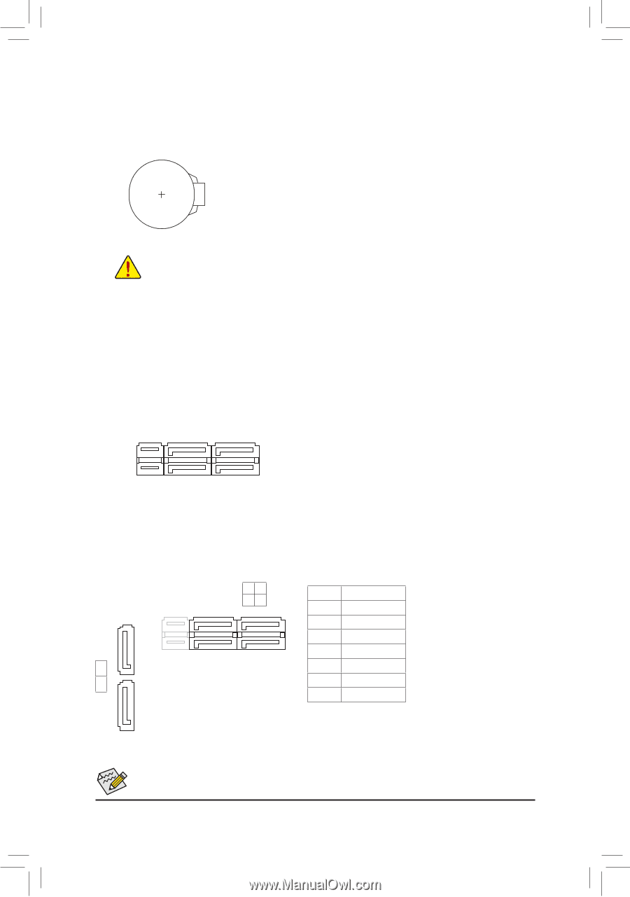
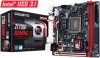
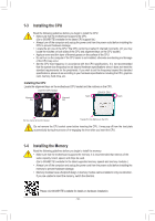
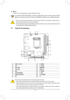
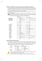
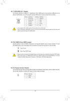
B SS B_ 1 1 23 1 1 23 1 1 23 1 1 23 1 1 23 1 1 23 1 _S 5) BAT (Battery) The battery provides power to keep the values (such as BIOS configurations, date, and time information) in the CMOS when the computer is turned off. Replace the battery when the batteBrySvSoltage drops to a low B_ level, or the CMOS values may not be accurate or may be lost. S 1 You may clear the CMOS values by removing the battery: _S 1. Turn off your computer and unplug the power cord. 2. Gently remove the battery from the battery holder and wait for one minute. (Or use a metal object like a screwdriver to touch the positive1a2n3d negative terminals of the battery holder, maSking them short for 5 seconds.) 3. Replace the battery. S 4. Plug in the power cord and restart your computer. •• Always turn off your computer and unplug the power cord before replacing the battery. •• Replace the battery with an equivalent one. Danger of explosion if the battery is replaced with 1 23 an incorrect model. •• Contact the place of purchase or local dealer if ySou are not able to replace the battery by yourself or uncertain about the battery model. •• When installing the battery, note the orientation of the positive side (+) and the negative side (-) of the battery (the positive side should face up). •• Used batterSies 3must be handled in accoBrdSaSnce wSith local environmental regUulations. __ 3 6) SATA EXPRESS (SATA Express Connector) Each SATA Express connector supports a single SATA Express device. S_ S3 SB FS S S U _ __ 3 S_ 7) SATA3 0/1/2/3/4/5 (SATA 6Gb/s Connectors) The SATA connectors conform to SATA 6Gb/s sBt_andard and SF are compatible wi_th SATA _ 3Gb/s and SATA 1.5Gb/s standard. Each SATA connector supports a single SATA device. The Intel® Chipset supports RAID 0, RAID 1, RAID 5, and RAID 10. Refer to Chapter 3, "Configuring a RAID Set," for instructions on configuring a RAID array. SATA3 S _ 32 SATA3 10 Pin No. Definition 1 B_ GND _ 1 7 1 2 TXP 7 1 3 TXN 4 GND 4 5 S_ 5 RXN 6 RXP 7 GND DEBUG PORT 7 To enable hot-plugging for the SATA ports, refer to Chapter 2, "BIOS Setup," "Peripherals\SATA CoSnfig_uration," for more information. - 15 - _ _B _ _B DEBUG PORT S_
-
 1
1 -
2
-
3
-
4
-
5
-
6
-
7
-
8
-
9
-
 10
10 -
 11
11 -
 12
12 -
 13
13 -
 14
14 -
 15
15 -
 16
16 -
 17
17 -
 18
18 -
 19
19 -
 20
20 -
21
-
22
-
23
-
24
-
25
-
26
-
27
-
28
-
29
-
30
-
31
-
32
-
33
-
34
-
35
-
36
-
37
-
38
-
39
-
40
-
41
-
42
-
43
-
44
 |
 |