Gigabyte GA-Z170X-Gaming 6 User Manual - Page 17
BAT Battery, SPDIF_O S/PDIF Out Header, M2D_32G/M2H_32G M.2 Socket 3 Connectors
 |
View all Gigabyte GA-Z170X-Gaming 6 manuals
Add to My Manuals
Save this manual to your list of manuals |
Page 17 highlights
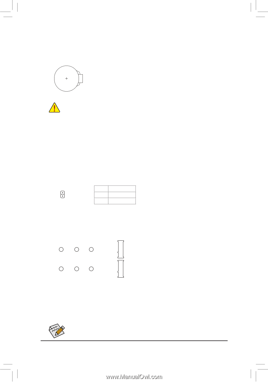
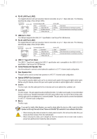
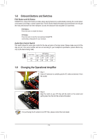
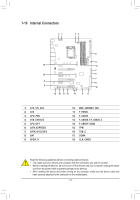
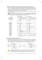
8) BAT (Battery) The battery provides power to keep the values (such as BIOS configurations, date, and time information) in the CMOS when the computer is turned off. Replace the battery when the battery voltage drops to a low level, or the CMOS values may not be accurate or may be lost. You may clear the CMOS values by removing the battery: 1. Turn off your computer and unplug the power cord. 2. Gently remove the battery from the battery holder and wait for one minute. (Or use a metal object like a screwdriver to touch the positive and negative terminals of the battery holder, making them short for 5 seconds.) 3. Replace the battery. 4. Plug in the power cord and restart your computer. S•• ASlwaysU turn off your computer and unplug the power cord before replacing the battery. •• Replace the battery with an equivalent one. Danger of explosion if the battery is replaced with an incorrect model. S•• CSontacUt the place of purchase or local dealer if you are not able to replace the battery by yourself or uncertain about the battery model. •• When installing the battery, note the orientation of the positive side (+) and the negative side (-) of the battery (the positive side should face up). •• Used batteries must be handled in accordance with local environmental regulations. 123 123 9) SPDIF_O (S/PDIF Out Header) This header supports digital S/PDIF Out and connects a S/PDIF digital audio cable (provided by expansion cards) for digital audio output from your motherboard to certain expansion cards like graphics cards and sound cards. For example, some graphics cards may require you to use a S/PDIF digital audio cable for digital audio output from your motherboard to your graphics card if you wish to connect an HDMI display to the graphics card and have digital audio output from the HDMI display at the same time. For information about connecting the S/PDIF digital audio cable, carefully read the manual for your expansion card. Pin No. Definition B S_ B1 1 SPDIFO 2 GND 10) M2D_B32S_G/M2H_32G (M.2 Socket 3 Connectors) The M.2 cBonnectors support M.2 SATA SSDs and M.2 PCIe SSDs and support RAID configuration through the Intel® Chipset. Please note that an M.2 PCIe SSD cannot be used to create a RAID set either with an M.2 SATA SSD or a SATA hard drive. To create a RAID array with an M.2 PCIe SSD, you must set up the configuration in UEFI BIOS mode. Refer to Chapter 3S, "Configuring a RAID Set," for instructions on configuring a RAID array. S 80D 60D 42D M2D_32G S S 80H 60H 42H M2H_32G Follow the steps below to correctly install an M.2 SSD in the M.2 connector. Step 1: Use a screw driver to unfasFten the screw and nut from the motherboard. Locate the proper mounting hole for the M.2 SSD to be installed and then screw the nut first. Step 2: Slide the M.2 SSD into the connector at an angle. Step 3: F Press the M.2 SSD down and then secure it with the screw. On the mother_b0oard there are three length adjustment holes for the M.2 SSD. Select the proper hole for the M.2 SSD to be installed and refasten the screw and nut. - 17 - _0 _F
-
 1
1 -
2
-
3
-
4
-
5
-
6
-
7
-
8
-
9
-
10
-
11
-
 12
12 -
 13
13 -
 14
14 -
 15
15 -
 16
16 -
 17
17 -
 18
18 -
 19
19 -
 20
20 -
 21
21 -
 22
22 -
23
-
24
-
25
-
26
-
27
-
28
-
29
-
30
-
31
-
32
-
33
-
34
-
35
-
36
-
37
-
38
-
39
-
40
-
41
-
42
-
43
-
44
-
45
-
46
-
47
-
48
 |
 |