Gigabyte GA-Z68XP-UD4 User Manual - Page 20
Back Panel Connectors
 |
UPC - 818313013040
View all Gigabyte GA-Z68XP-UD4 manuals
Add to My Manuals
Save this manual to your list of manuals |
Page 20 highlights
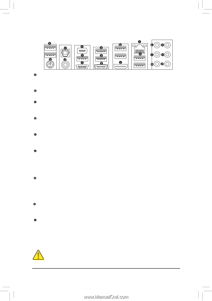
1-7 Back Panel Connectors USB 2.0/1.1 Port The USB port supports the USB 2.0/1.1 specification. Use this port for USB devices such as a USB key- board/mouse, USB printer, USB flash drive and etc. PS/2 Keyboard/Mouse Port Use this port to connect a PS/2 mouse or keyboard. Optical S/PDIF Out Connector This connector provides digital audio out to an external audio system that supports digital optical audio. Before using this feature, ensure that your audio system provides an optical digital audio in connector. Coaxial S/PDIF Out Connector This connector provides digital audio out to an external audio system that supports digital coaxial audio. Before using this feature, ensure that your audio system provides a coaxial digital audio in connector. IEEE 1394a Port The IEEE 1394 port supports the IEEE 1394a specification, featuring high speed, high bandwidth and hotplug capabilities. Use this port for an IEEE 1394a device. eSATA/USB Combo Connector This connector supports SATA 6Gb/s and USB 2.0/1.1 specification. Use the port to connect an external SATA device or a SATA port multiplier. The Marvell 88SE9172 chip supports RAID function. Refer to Chapter 5, "Configuring SATA Hard Drive(s)," for instructions on configuring a RAID array. Or use this port for USB devices such as a USB keyboard/mouse, USB printer, USB flash drive and etc. eSATA 6Gb/s Connector The eSATA 6Gb/s port conforms to SATA 6Gb/s standard and is compatible with SATA 3Gb/s and SATA 1.5Gb/s standard. Use the port to connect an external SATA device or a SATA port multiplier. The Mar- vell 88SE9172 chip supports RAID function. Refer to Chapter 5, "Configuring SATA Hard Drive(s)," for instructions on configuring a RAID array. USB 3.0/2.0 Port The USB 3.0 port supports the USB 3.0 specification and is compatible to the USB 2.0/1.1 specification. Use this port for USB devices such as a USB keyboard/mouse, USB printer, USB flash drive and etc. HDMI Port HDMI (High-Definition Multimedia Interface) is an all-digital audio/video interface capable of transmitting uncompressed audio/video signals. The HDMI port is HDCP compliant and supports Dolby TrueHD and DTS HD Master Audio formats. You can use this port to connect your HDMI-supported audio/video device. The maximum supported resolution is 1920x1200, but the actual resolutions supported are dependent on the monitor being used. •• When removing the cable connected to a back panel connector, first remove the cable from your device and then remove it from the motherboard. •• When removing the cable, pull it straight out from the connector. Do not rock it side to side to prevent an electrical short inside the cable connector. Hardware Installation - 20 -
-
 1
1 -
2
-
3
-
4
-
5
-
6
-
7
-
8
-
9
-
10
-
11
-
12
-
13
-
14
-
 15
15 -
 16
16 -
 17
17 -
 18
18 -
 19
19 -
 20
20 -
 21
21 -
 22
22 -
 23
23 -
 24
24 -
 25
25 -
26
-
27
-
28
-
29
-
30
-
31
-
32
-
33
-
34
-
35
-
36
-
37
-
38
-
39
-
40
-
41
-
42
-
43
-
44
-
45
-
46
-
47
-
48
-
49
-
50
-
51
-
52
-
53
-
54
-
55
-
56
-
57
-
58
-
59
-
60
-
61
-
62
-
63
-
64
-
65
-
66
-
67
-
68
-
69
-
70
-
71
-
72
-
73
-
74
-
75
-
76
-
77
-
78
-
79
-
80
-
81
-
82
-
83
-
84
-
85
-
86
-
87
-
88
-
89
-
90
-
91
-
92
-
93
-
94
-
95
-
96
-
97
-
98
-
99
-
100
-
101
-
102
-
103
-
104
-
105
-
106
-
107
-
108
-
109
-
110
-
111
-
112
-
113
-
114
-
115
-
116
-
117
-
118
-
119
-
120
 |
 |