Gigabyte GS-R12P4G Manual - Page 32
Intel LGA2011 socket Secondary CPU
 |
View all Gigabyte GS-R12P4G manuals
Add to My Manuals
Save this manual to your list of manuals |
Page 32 highlights
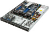
Item Code 1 USB_A1 2 ATX1 3 P12V_AUX2 4 PWR_DET1 5 CPU1_FAN 6 DDR3_P1_E0 7 DDR3_P1_E1 8 DDR3_P1_F0 9 DDR3_P1_F1 10 CPU1 11 P12V_AUX1 12 DDR3_P1_H1 13 DDR3_P1_H0 14 DDR3_P1_G1 15 DDR3_P1_G0 16 DDR3_P0_A0 17 DDR3_P0_A1 18 DDR3_P0_B0 19 DDR3_P0_B1 20 CPU0 21 BAT1 22 CPU0_FAN 23 DDR3_P0_D1 24 DDR3_P0_D0 25 DDR3_P0_C1 26 DDR3_P0_C0 27 BP_1 28 FP_1 29 SATA1 30 SATA_DOM1 31 SATA2 32 SATA_DOM2 33 SATA3/SATA4/SATA5/SATA6 34 FRONT_USB 35 COM2 36 MINI_CN2 37 MINI_CN1 38 BIOS_WP1 39 BMC_FRB1 40 BIOS_RVCR1 Description Type A USB connector 24 pin power connector 8 pin power connector PMBus connector CPU1 fan cable connector Channel 1 slot 0 (for secondary CPU) Channel 1 slot 1 (for secondary CPU) Channel 2 slot 0 (for secondary CPU) Channel 2 slot 1 (for secondary CPU) Intel LGA2011 socket (Secondary CPU) 8 pin power connector Channel 4 slot 1 (for secondary CPU) Channel 4 slot 0 (for secondary CPU) Channel 3 slot 1 (for secondary CPU) Channel 3 slot 0 (for secondary CPU) Channel 1 slot 0 (for primary CPU) Channel 1 slot 1 (for primary CPU) Channel 2 slot 0 (for primary CPU) Channel 2 slot 1 (for primary CPU) Intel LGA2011 socket (Primary CPU) Battery socket CPU0 fan cable connector Channel 4 slot 1 (for primary CPU) Channel 4 slot 0 (for primary CPU) Channel 3 slot 1 (for primary CPU) Channel 3 slot 0 (for primary CPU) HDD back plane board header Front panel header SATA 6Gb/s connector SATA1 port DOM support jumper SATA 6Gb/s connector SATA2 port DOM support jumper SATA 3Gb/s connectors USB 2.0 connectors Serial port cable connector Mini SAS cable connector Mini SAS cable connector BIOS write protect jumper Force to Stop FRB3 Timer jumper BIOS recovery jumper Hardware Installation - 32 -
-
 1
1 -
2
-
3
-
4
-
5
-
6
-
7
-
8
-
9
-
10
-
11
-
12
-
13
-
14
-
15
-
16
-
17
-
18
-
19
-
20
-
21
-
22
-
23
-
24
-
25
-
26
-
 27
27 -
 28
28 -
 29
29 -
 30
30 -
 31
31 -
 32
32 -
 33
33 -
 34
34 -
 35
35 -
 36
36 -
 37
37 -
38
-
39
-
40
-
41
-
42
-
43
-
44
-
45
-
46
-
47
-
48
-
49
-
50
-
51
-
52
-
53
-
54
-
55
-
56
-
57
-
58
-
59
-
60
-
61
-
62
-
63
-
64
-
65
-
66
-
67
-
68
-
69
-
70
-
71
-
72
-
73
-
74
 |
 |
