Gigabyte GS-R22PXL Manual - Page 33
Intel LGA1356 socket Secondary CPU
 |
View all Gigabyte GS-R22PXL manuals
Add to My Manuals
Save this manual to your list of manuals |
Page 33 highlights
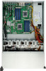
Item Code 1 ID_SW 2 MLAN 3 USB_LANB1 4 USB_LANB2 5 VGA_1 6 COM1 7 P12V_AUX2 8 CPU1 9 ATX1 10 DDR3_P0_A0 11 DDR3_P0_A1 12 DDR3_P0_B0 13 DDR3_P0_B1 14 DDR3_P0_C0 15 DDR3_P0_C1 16 PMBUS_CN_1 17 P12V_AUX1 18 CPU0 19 RAID_KEY2 20 BIOS_WP 21 LED2 22 MINI_CN2 23 MINI_CN1 24 SATA_SGPIO 25 SATA2/3/4/5 26 SATA0/1 27 SATA3_D 28 SATA2_D 29 SSB_ME1 30 BIOS_RVCR 31 PASSWORD 32 ROMST_FRB3 33 F_USB1 34 F_USB2 35 FP_1 36 COM2 Description ID switch BMC Management LAN port LAN1 port (top) / USB ports (bottom) LAN2 port (top) / USB ports (bottom) VGA port Serial port 8 pin power connector Intel LGA1356 socket (Secondary CPU) 24-pin power connector Channel 1 slot 0 (for primary CPU) Channel 1 slot 1 (for primary CPU) Channel 2 slot 0 (for primary CPU) Channel 2 slot 1 (for primary CPU) Channel 3 slot 0 (for primary CPU) Channel 3 slot 1 (for primary CPU) PM Bus connector 8 pin power connector Intel LGA1356 socket (Primary CPU) LSI RAID Select connector BIOS write protect jumper LSI Firmware Readiness LED Mini SAS connector Mini SAS connector SATA SGPIO connector SATA 3Gb/s connectors SATA 6Gb/s connectors SATA3 port DOM support jumper SATA2 port DOM support jumper ME enable/disable jumper BIOS recovery jumper Clear password jumper Force to Stop FRB3 Timer jumper Front USB connector Front USB connector Front panel connector Serial port connector - 33 - Hardware Installation
-
 1
1 -
2
-
3
-
4
-
5
-
6
-
7
-
8
-
9
-
10
-
11
-
12
-
13
-
14
-
15
-
16
-
17
-
18
-
19
-
20
-
21
-
22
-
23
-
24
-
25
-
26
-
27
-
 28
28 -
 29
29 -
 30
30 -
 31
31 -
 32
32 -
 33
33 -
 34
34 -
 35
35 -
 36
36 -
 37
37 -
 38
38 -
39
-
40
-
41
-
42
-
43
-
44
-
45
-
46
-
47
-
48
-
49
-
50
-
51
-
52
-
53
-
54
-
55
-
56
-
57
-
58
-
59
-
60
-
61
-
62
-
63
-
64
-
65
-
66
-
67
-
68
-
69
-
70
-
71
-
72
 |
 |
