Gigabyte H310M H 2.0 User Manual - Page 17
CLR_CMOS Clear CMOS Jumper, TPM Trusted Platform Module Header, BAT Battery
 |
View all Gigabyte H310M H 2.0 manuals
Add to My Manuals
Save this manual to your list of manuals |
Page 17 highlights
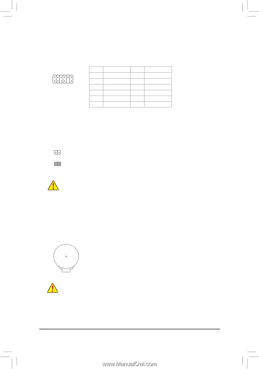
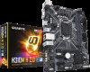
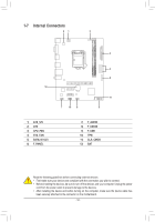
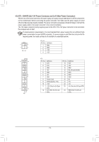
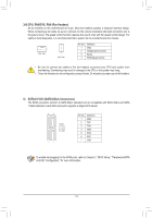
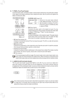
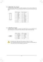
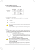
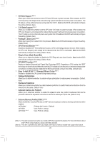
__ 3 B F F_USB3 F _ _B _0 10) TPM (Trusted Platform Module Header) You may connect a TPM (Trusted Platform Module) to this header. _ _F Pin No. Definition Pin No. Definition 11 1 1 LAD0 7 LAD3 12 2 2 VCC3 8 GND 3 LAD1 9 LFRAME 4 No Pin 5 LAD2 10 NC 11 SERIRQ _ 0 F 6 LCLK 12 LRESET 11) CLR_CMOS (Clear CMOS Jumper) Use this jumper to clear the BIOS configuration and reset the CMOS values to factory defaults. To clear S F_ the CMOS values, use a metal object like a screwdriver to touch the two pins for a few seconds. Open: Normal Short: Clear CMOS Values •• Always turn off your computer and unplug the power cord from the power outlet before clearing the CMOS values. _3 U •• After system restart, go to BIOS Setup to load factory defaults (select Load Optimized Defaults) or manually configure the BIOS settings (refer to Chapter 2, "BIOS Setup," for BIOS configurations). F_USB3 12) BAT (Battery) F_USBT3h0e3 battery provides power to keep the values (such as BIOS configurations, date, and time information) in the CMOS when the computer is turned off. Replace the battery when the battery voltage drops to a low level, or the CMOS values may not be accurate or may be lost. You may clear the CMOS values by removing the battery: 1. Turn off your computer and unplug the power cord. 2. Gently remove the battery from the battery holder and wait for one minute. (Or use a metal object like a screwdriver to touch the positive and negative terminals of the battery holder, making them short for 5 seconds.) 3. Replace the battery. 4. Plug in the power cord and restart your computer. •• Always turn off your computer and unplug the power cord before replacing the battery. •• Replace the battery with an equivalent one. Damage to your devices may occur if the battery is replaced with an incorrect model. •• Contact the place of purchase or local dealer if you are not able to replace the battery by yourself or uncertain about the battery model. •• When installing the battery, note the orientation of the positive side (+) and the negative side (-) of the battery (the positive side should face up). •• Used batteries must be handled in accordance with local environmental regulations. - 17 -
-
 1
1 -
2
-
3
-
4
-
5
-
6
-
7
-
8
-
9
-
10
-
11
-
 12
12 -
 13
13 -
 14
14 -
 15
15 -
 16
16 -
 17
17 -
 18
18 -
 19
19 -
 20
20 -
 21
21 -
 22
22 -
23
-
24
-
25
-
26
-
27
-
28
-
29
-
30
-
31
-
32
-
33
-
34
-
35
-
36
-
37
-
38
-
39
-
40
 |
 |