Gigabyte MD70-HB2 Manual - Page 7
LSI RAID key header MD70-HB0 Only
 |
View all Gigabyte MD70-HB2 manuals
Add to My Manuals
Save this manual to your list of manuals |
Page 7 highlights
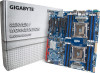
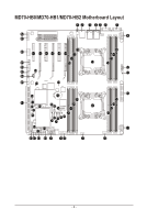
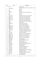
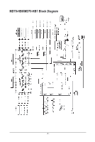
Item 1 SW_ID Code 2 USB3_MLAN1 3 LAN1 4 LAN2 5 CPU1_FAN 6 VGA 7 COM1 8 P12V_AUX2 9 DIMM_P1_G0 10 DIMM_P1_G1 11 DIMM_P1_H0 12 DIMM_P1_H1 13 CPU1 14 PMBUS 15 PMBUS_SEL 16 ATX1 17 DIMM_P0_A0 18 DIMM_P0_A1 19 DIMM_P0_B0 20 DIMM_P0_B1 21 P12V_AUX1 22 CPU0 23 SYS_FAN5 24 CPU0_FAN 25 DIMM_P0_D1 26 DIMM_P0_D0 27 DIMM_P0_C1 28 DIMM_P0_C0 29 ME_UPDATE 30 BMC_FRB 31 ME_RCVR 32 BIOS_WP 33 BIOS_PWD 34 BIOS_RCVR 35 LSI_UART1 36 SW_RAID 37 SYS_FAN4 38 SYS_FAN3 39 MSAS_HD_1 40 SATA_SGP 41 IMR_KEY 42 SSATA_SGP 43 FP_1 Description ID switch button BMC Management LAN port (top) / USB 3.0 ports (bottom) LAN1 port LAN2 port CPU1 fan connector (for Secondary CPU) VGA port Serial port 8 pin power connector (for secondary CPU) Channel 3 slot 0 (for secondary CPU) Channel 3 slot 1 (for secondary CPU) Channel 4 slot 0 (for secondary CPU) Channel 4 slot 1 (for secondary CPU) Intel LGA2011 Socket R (Secondary CPU) PMBus connector PMBus power select jumper 24 pin main power connector Channel 1 slot 0 (for primary CPU) Channel 1 slot 1 (for primary CPU) Channel 2 slot 0 (for primary CPU) Channel 2 slot 1 (for primary CPU) 8 pin power connector (for primary CPU) Intel LGA2011 Socket R (Primary CPU) System fan connector#5 CPU0 fan connector (for Primary CPU) Channel 4 slot 1 (for primary CPU) Channel 4 slot 0 (for primary CPU) Channel 3 slot 1 (for primary CPU) Channel 3 slot 0 (for primary CPU) ME update jumper Force to Stop FRB Timer jumper ME recovry jumper BIOS write protect jumper Clearing Supervisor Password jumper BIOS recovery jumper LSI UART header Intel Software RAID Key jumper System fan connector#4 System fan connector#3 Mini-SAS HD connector (MD70-HB0 Only) SATA SGPIO header LSI RAID key header (MD70-HB0 Only) sSATA SGPIO header Front panel header - 7 -
-
 1
1 -
 2
2 -
 3
3 -
 4
4 -
 5
5 -
 6
6 -
 7
7 -
 8
8 -
 9
9 -
 10
10 -
 11
11 -
 12
12 -
13
-
14
-
15
-
16
-
17
-
18
-
19
-
20
-
21
-
22
-
23
-
24
-
25
-
26
-
27
-
28
-
29
-
30
-
31
-
32
-
33
-
34
-
35
-
36
-
37
-
38
-
39
-
40
-
41
-
42
-
43
-
44
-
45
-
46
-
47
-
48
-
49
-
50
-
51
-
52
-
53
-
54
-
55
-
56
-
57
-
58
-
59
-
60
-
61
-
62
-
63
-
64
-
65
-
66
-
67
-
68
-
69
-
70
-
71
-
72
-
73
-
74
-
75
-
76
-
77
-
78
-
79
-
80
-
81
-
82
-
83
-
84
-
85
-
86
-
87
-
88
-
89
-
90
-
91
-
92
-
93
-
94
-
95
-
96
-
97
-
98
-
99
-
100
-
101
-
102
-
103
-
104
-
105
-
106
-
107
-
108
-
109
-
110
-
111
-
112
-
113
-
114
-
115
-
116
-
117
-
118
-
119
-
120
-
121
-
122
-
123
-
124
-
125
-
126
-
127
-
128
-
129
-
130
 |
 |