Gigabyte MD70-HB2 Manual - Page 8
LSI firmware readiness LED MD70-HB0 Only, BMC firmware readiness LED
 |
View all Gigabyte MD70-HB2 manuals
Add to My Manuals
Save this manual to your list of manuals |
Page 8 highlights
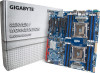
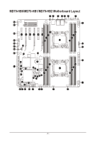
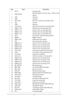
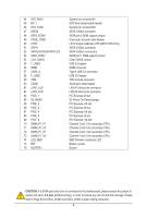
44 SYS_FAN1 45 BP_1 46 SYS_FAN2 47 SATA0 48 SATA_DOM0 49 CASE_OPEN 50 LED5 51 SATA1 52 SATA2/3/4/5/SSATA0/1/2/3 53 SATA_DOM1 54 CLR_CMOS 55 F_USB3 56 IPMB 57 USB3_A 58 F_USB2 59 TPM 60 COM2 61 LAN1_LED 62 LAN2_LED 63 PCIE_1 64 S3_MASK 65 PCIE_2 66 PCIE_3 67 PCIE_4 68 PCIE_5 69 PCIE_6 70 DIMM_P1_F1 71 DIMM_P1_F0 72 DIMM_P1_E1 73 DIMM_P1_E0 74 LED_BMC 75 BAT 76 BUZZER1 System fan connector#1 HDD back plane board header System fan connector#2 SATA 3 6Gb/s connector SATA port 0 DOM support jumper Case open intrusion alert header LSI firmware readiness LED (MD70-HB0 Only) SATA 3 6Gb/s connector SATA 3 6Gb/s connectors SATA port 1 DOM support jumper Clear CMOS jumper USB 3.0 header IPMB connector Type A USB 3.0 connector USB 2.0 header TPM module connector Serial port cable header LAN #1 Active/Link connector LAN #2 Active/Link connector PCI Express x8 slot S3 Power On Select jumper PCI Express x16 slot PCI Express x8 slot PCI Express x16 slot PCI Express x8 slot PCI Express x16 slot Channel 3 slot 1 (for secondary CPU) Channel 3 slot 0 (for secondary CPU) Channel 4 slot 1 (for secondary CPU) Channel 4 slot 0 (for secondary CPU) BMC firmware readiness LED Battery socket Buzzer CAUTION! If a SATA type hard drive is connected to the motherboard, please ensure the jumper is closed and set to 2-3 pins (Default setting), in order to reduce any risk of hard disk damage. Please refer to Page 38 for SATA_DOM0 and SATA_DOM1 jumper setting instruction. - 8 -
-
 1
1 -
2
-
 3
3 -
 4
4 -
 5
5 -
 6
6 -
 7
7 -
 8
8 -
 9
9 -
 10
10 -
 11
11 -
 12
12 -
 13
13 -
14
-
15
-
16
-
17
-
18
-
19
-
20
-
21
-
22
-
23
-
24
-
25
-
26
-
27
-
28
-
29
-
30
-
31
-
32
-
33
-
34
-
35
-
36
-
37
-
38
-
39
-
40
-
41
-
42
-
43
-
44
-
45
-
46
-
47
-
48
-
49
-
50
-
51
-
52
-
53
-
54
-
55
-
56
-
57
-
58
-
59
-
60
-
61
-
62
-
63
-
64
-
65
-
66
-
67
-
68
-
69
-
70
-
71
-
72
-
73
-
74
-
75
-
76
-
77
-
78
-
79
-
80
-
81
-
82
-
83
-
84
-
85
-
86
-
87
-
88
-
89
-
90
-
91
-
92
-
93
-
94
-
95
-
96
-
97
-
98
-
99
-
100
-
101
-
102
-
103
-
104
-
105
-
106
-
107
-
108
-
109
-
110
-
111
-
112
-
113
-
114
-
115
-
116
-
117
-
118
-
119
-
120
-
121
-
122
-
123
-
124
-
125
-
126
-
127
-
128
-
129
-
130
 |
 |
