Gigabyte MN525BI Manual - Page 14
FAN1/FAN2 CPU Fan/System Fan Headers, F_PANEL Front Panel Header
 |
View all Gigabyte MN525BI manuals
Add to My Manuals
Save this manual to your list of manuals |
Page 14 highlights
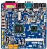
2/3) FAN1/FAN2 (CPU Fan/System Fan Headers) The motherboard has a 4-pin CPU fan header (FAN1), a 4-pin (FAN2) system fan headers. Most fan headers possess a foolproof insertion design. When connecting a fan cable, be sure to connect it in the correct orientation (the black connector wire is the ground wire). The motherboard supports CPU fan speed control, which requires the use of a CPU fan with fan speed control design. For optimum heat dissipation, it is recommended that a system fan be installed inside the chassis. FAN1 FAN2 FAN1 FAN2 FAN1 (CPU Fan): Pin No. Definition 1 GND 2 +12V / Speed Control 3 Sense 4 Speed Control FAN2 (System Fan): Pin No. Definition 1 GND 2 +12V / Speed Control 3 Sense 4 Speed Control • Be sure to connect fan cables to the fan headers to prevent your CPU and system from overheating. Overheating may result in damage to the CPU or the system may hang. • These fan headers are not configuration jumper blocks. Do not place a jumper cap on the headers. 5) F_PANEL (Front Panel Header) Connect the power switch, reset switch, speaker, chassis intrusion switch/sensor and system status indicator on the chassis to this header according to the pin assignments below. Note the positive and negative pins before connecting the cables. 2 12 1 11 Pin No. 1 2 3 4 5 6 7 8 9 10 11 12 - 14 - Signal Name HD+ MSG+ HD- MSG- RST+ PW+ RST- PW- ACT+ ACT+ ACT- ACT- Definition Hard Disk LED Signal (+) Message LED Signal (+) Hard Disk LED Signal (-) Message LED Signal (-) Reset Button (+) Power Switch (+) Reset Button (-) Power Switch (-) LAN1 Act LED Signal (+) LAN 2Act LED Signal (+) LAN1 Act LED Signal (-) LAN2 Act LED Signal (-) Hardware Installation
-
 1
1 -
2
-
3
-
4
-
5
-
6
-
7
-
8
-
 9
9 -
 10
10 -
 11
11 -
 12
12 -
 13
13 -
 14
14 -
 15
15 -
 16
16 -
 17
17 -
 18
18
 |
 |
