Gigabyte MN525BI Manual - Page 15
SATAII1/2/3/4/5 SATA 3Gb/s Connectors, 8 F_USB1/F_USB2 USB Headers
 |
View all Gigabyte MN525BI manuals
Add to My Manuals
Save this manual to your list of manuals |
Page 15 highlights
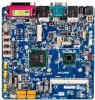
PORT DEBUG PORT 6) SATAII1/2/3/4/5 (SATA 3Gb/s Connectors) The SF_APTAANEcLonnectors conform to SATA 3Gb/s standard anFd_AaUreDIOcompatible with SATA 1.5Gb/s standard. Each SATA connector supports a single SATA device. Smart Card 7 1 F_PANEL SATAII5 SATAII1 F_PANEL SATAII4 SATAII3 SATAII2 Pin No. Definition F_AUDIO 1 GND 2 TXP 3 TXN 4 GND 5 RXN F 6 RXP F 7 GND IR/CIR • A RAID 0 or RAID 1 configuration requires at least two hard drives. If more than two hard drives are configured, the total number of hard drives must be an even number. F_P•ANEAL RAID 5 configuration requires at least three hard drives. (The total number of hard drives does not have to be an even number.) • A RAID 10 configuration requires four hard drives. IR (Note) When a RAID configuration is built across the SATA 3Gb/s channels, the system performance of the RAID configuration may vary depends on the devices are connected. C 7/8) F_USB1/F_USB2 (USB Headers) The headers conform to USB 2.0/1.1 specification. Each USB header can provide two USB ports via an optional USB bracket. For purchasing the optional USB bracket, please contact the local dealer. PWR_LED 2 10 F_USB 1 9 CLR_CMOS BIOS_WP CLR_CMOS BIOS_WP CI Pin No. 1 2 3 4 SUR_CEN5 6 7 8 9 10 Definition Power (5V) Power (5V) USB DXUSB DYUSB DX+ USB DY+ GND GND No Pin NC WCLhRe_nPWthDe system is in S4/S5 mode, only the USB ports routed to the F_USB1 header can support the ON/OFF Charge function. - 15 - MODEM Hardware Installation DPVRM
-
 1
1 -
2
-
3
-
4
-
5
-
6
-
7
-
8
-
9
-
 10
10 -
 11
11 -
 12
12 -
 13
13 -
 14
14 -
 15
15 -
 16
16 -
 17
17 -
 18
18
 |
 |
