Gigabyte MW70-3S0 Manual - Page 8
S3 Power On Select jumper
 |
View all Gigabyte MW70-3S0 manuals
Add to My Manuals
Save this manual to your list of manuals |
Page 8 highlights
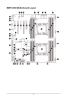
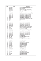
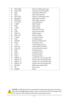
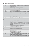
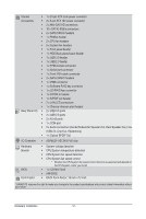
44 SATA_DOM0 45 CASE_OPEN 46 LED5 47 SATA1 48 SATA_DOM1 49 SATA2/3/4/5 50 SSATA0/1/2/3 51 CLR_CMOS 52 F_USB3 53 IPMB 54 F_USB2 55 TPM 56 COM2 57 SPDIF_IN1 58 SPDIF_OUT 59 F_AUDIO 60 PCIE_1 61 S3_MASK 62 PCIE_2 63 F_VGA 64 LAN1_LED 65 LAN2_LED 66 PCIE_3 67 PCIE_4 68 PCIE_5 69 PCIE_6 70 DIMM_P1_F1 71 DIMM_P1_F0 72 DIMM_P1_E1 73 DIMM_P1_E0 74 LED_BMC 75 BAT 76 BUZZER1 SATA port 0 DOM support jumper Case open intrusion alert header LSI firmware readiness LED SATA 3 6Gb/s connector SATA port 1 DOM support jumper SATA 3 6Gb/s connectors SATA 3 6Gb/s connectors Clear CMOS jumper USB 3.0 header IPMB connector USB 2.0 header TPM module connector Serial port cable header S/PDIF in header S/PDIF out header Front audio connector PCI Express x8 slot S3 Power On Select jumper PCI Express x16 slot Front VGA cable connector LAN #1 Active/Link connector LAN #2 Active/Link connector PCI Express x8 slot PCI Express x16 slot PCI Express x8 slot PCI Express x16 slot Channel 3 slot 1 (for secondary CPU) Channel 3 slot 0 (for secondary CPU) Channel 4 slot 1 (for secondary CPU) Channel 4 slot 0 (for secondary CPU) BMC firmware readiness LED Battery socket Buzzer CAUTION! If a SATA type hard drive is connected to the motherboard, please ensure the jumper is closed and set to 2-3 pins (Default setting), in order to reduce any risk of hard disk damage. Please refer to Page 39 for SATA_DOM0 and SATA_DOM1 jumper setting instruction. - 8 -
-
 1
1 -
2
-
 3
3 -
 4
4 -
 5
5 -
 6
6 -
 7
7 -
 8
8 -
 9
9 -
 10
10 -
 11
11 -
 12
12 -
 13
13 -
14
-
15
-
16
-
17
-
18
-
19
-
20
-
21
-
22
-
23
-
24
-
25
-
26
-
27
-
28
-
29
-
30
-
31
-
32
-
33
-
34
-
35
-
36
-
37
-
38
-
39
-
40
-
41
-
42
 |
 |