Gigabyte P55-UD3L User Manual - Page 11
x audio jacks Line In/Line Out/Microphone, PnP 1.0a, DMI 2.0, SM BIOS 2.4, ACPI 1.0b
 |
View all Gigabyte P55-UD3L manuals
Add to My Manuals
Save this manual to your list of manuals |
Page 11 highlights
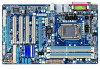
USB Chipset - Up to 12 USB 2.0/1.1 ports (8 on the back panel, 4 via the USB brackets connected to the internal USB headers) Internal w 1 x 24-pin ATX main power connector Connectors w 1 x 4-pin ATX 12V power connector w 1 x floppy disk drive connector w 1 x IDE connector w 8 x SATA 3Gb/s connectors w 1 x CPU fan header w 2 x system fan headers w 1 x power fan header w 1 x front panel header w 1 x front panel audio header w 1 x CD In connector w 1 x S/PDIF In header w 1 x S/PDIF Out header w 2 x USB 2.0/1.1 headers w 1 x clearing CMOS jumper Back Panel w 1 x PS/2 keyboard or PS/2 mouse port Connectors w 1 x coaxial S/PDIF Out connector w 1 x parallel port w 1 x serial port w 8 x USB 2.0/1.1 ports w 1 x RJ-45 port w 3 x audio jacks (Line In/Line Out/Microphone) I/O Controller w iTE IT8720 chip Hardware Monitor w w w w w w BIOS w w w w System voltage detection CPU/System temperature detection CPU/System/Power fan speed detection CPU overheating warning CPU/System/Power fan fail warning CPU/System fan speed control (Note 6) 2 x 16 Mbit flash Use of licensed AWARD BIOS Support for DualBIOS™ PnP 1.0a, DMI 2.0, SM BIOS 2.4, ACPI 1.0b - 11 - Hardware Installation
-
 1
1 -
2
-
3
-
4
-
5
-
 6
6 -
 7
7 -
 8
8 -
 9
9 -
 10
10 -
 11
11 -
 12
12 -
 13
13 -
 14
14 -
 15
15 -
 16
16 -
17
-
18
-
19
-
20
-
21
-
22
-
23
-
24
-
25
-
26
-
27
-
28
-
29
-
30
-
31
-
32
-
33
-
34
-
35
-
36
-
37
-
38
-
39
-
40
-
41
-
42
-
43
-
44
-
45
-
46
-
47
-
48
-
49
-
50
-
51
-
52
-
53
-
54
-
55
-
56
-
57
-
58
-
59
-
60
-
61
-
62
-
63
-
64
-
65
-
66
-
67
-
68
-
69
-
70
-
71
-
72
-
73
-
74
-
75
-
76
-
77
-
78
-
79
-
80
-
81
-
82
-
83
-
84
-
85
-
86
-
87
-
88
-
89
-
90
-
91
-
92
-
93
-
94
-
95
-
96
-
97
-
98
-
99
-
100
-
101
-
102
-
103
-
104
-
105
-
106
-
107
-
108
-
109
-
110
-
111
-
112
 |
 |
