Gigabyte X399 AORUS Gaming 7 Users Manual - Page 29
LED_C1/LED_C2 RGB RGBW LED Strip Headers, SATA3 0/1/2/3/4/5/6/7 SATA 6Gb/s Connectors
 |
View all Gigabyte X399 AORUS Gaming 7 manuals
Add to My Manuals
Save this manual to your list of manuals |
Page 29 highlights
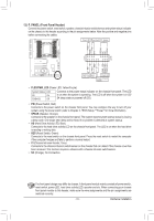
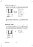
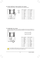
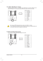
B_ S _S _ _ _B _ B_ S _S _ 10) LED_C1/LED_C2 (RGB (RGBW) LED Strip Headers) The header can be used to connect a standard 5050 RGB (RGBW) LED strip (12V/G/R/B/W), with maximum power rating of 2A (12V) and maximum length of 2m. LED_C2 _ 1 LED_C1 _ 1 Pin No. 1 2 3 4 5 Definition 12V G R B W Connect one end of the RGB (RGBW) LED strip extension cable to the header and the other end to your RGB (RGBW) LED strip. The black wire (marked with a triangle on the plug) of the extension cable must be connected to Pin 1 (12V) of this header. The 12V pin (marked with an arrow) on the other end of the extension cable must be lined up with the 12V of the LED strip. Be careful with the connection orientation of RGBW RGB the LED strip; incorrect connection may lead to the damage of the LED LED Strip LED Strip strip. If you are connecting a RGBW LED strip (5-pin), combine the 1 12V two plugs of the extension cable together first. If you are connecting a RBG_B LED strip (4-pin), useF_oUnSlBy3the 4-pin plug of the extension cable. B_ For how to tuUrSnBo0n_/Boff the lights of the LED strip, refer to the instructions on in Chapter 2, "BIOS Setup," "Peripherals," or Chapter 5, "Unique Features,"F"_AUPSBP3 Center\RGB Fusion." B_ Before installing the devices, be sure to turn off the devices and your computer. Unplug the power B_ cord from theUpSoBw0_eBr outlet to prevent damage to the devices. 11) SATA3 0/1/2/3/4/5/6/7 (SATA 6Gb/s Connectors) The SATA connectors conform to SATA 6Gb/s standard and are compatible with SATA 3Gb/s and SATA 1.5Gb/s standard. Each SATA connector supports a single SATA device. The AMD Chipset supports RAID 0, RAID 1, and RAID 10. Refer to Chapter 3, "Configuring a RAID Set," for instructions on configuring a RAID array. 0246 SATA3 1 3 5 7 7 1 7 1 Pin No. 1 2 3 4 5 6 7 Definition GND TXP TXN GND RXN RXP GND DEBUG PORT DEBUG PORT DEBUG PORT DEBUG PORT DEBUG PORT DEBUG PORT DEBUG PORT DEBUG PORT - 29 - Hardware Installation
-
 1
1 -
2
-
3
-
4
-
5
-
6
-
7
-
8
-
9
-
10
-
11
-
12
-
13
-
14
-
15
-
16
-
17
-
18
-
19
-
20
-
21
-
22
-
23
-
 24
24 -
 25
25 -
 26
26 -
 27
27 -
 28
28 -
 29
29 -
 30
30 -
 31
31 -
 32
32 -
 33
33 -
 34
34 -
35
-
36
-
37
-
38
-
39
-
40
-
41
-
42
-
43
-
44
-
45
-
46
-
47
-
48
-
49
-
50
-
51
-
52
-
53
-
54
-
55
-
56
-
57
-
58
-
59
-
60
-
61
-
62
-
63
-
64
-
65
-
66
-
67
-
68
-
69
-
70
-
71
-
72
-
73
-
74
-
75
-
76
-
77
-
78
-
79
-
80
-
81
-
82
-
83
-
84
-
85
-
86
-
87
-
88
-
89
-
90
-
91
-
92
-
93
-
94
-
95
-
96
-
97
-
98
-
99
-
100
-
101
-
102
-
103
-
104
-
105
-
106
-
107
-
108
-
109
-
110
-
111
-
112
-
113
-
114
-
115
-
116
-
117
-
118
-
119
-
120
-
121
-
122
-
123
-
124
 |
 |
