Gigabyte Z590 AORUS XTREME WATERFORCE User Manual - Page 23
Back Panel Connectors, Q-Flash Plus Button, Clear CMOS Button, SMA Antenna Connectors 2T2R
 |
View all Gigabyte Z590 AORUS XTREME WATERFORCE manuals
Add to My Manuals
Save this manual to your list of manuals |
Page 23 highlights
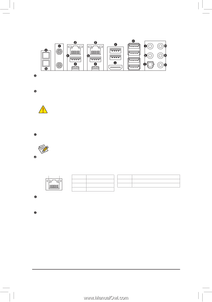
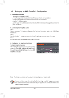
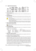
1-7 Back Panel Connectors Q-Flash Plus Button (Note) This button allows you to update the BIOS when the power connector is connected but the system is not powered on. Clear CMOS Button Use this button to clear the CMOS values (e.g. BIOS configuration) and reset the CMOS values to factory defaults when needed. •• Always turn off your computer and unplug the power cord from the power outlet before using the clear CMOS button. •• Do not use the clear CMOS button when the system is on, or the system may shutdown and data loss or damage may occur. •• After system restart, go to BIOS Setup to load factory defaults (select Load Optimized Defaults) or manually configure the BIOS settings (refer to Chapter 2, "BIOS Setup," for BIOS configurations). SMA Antenna Connectors (2T2R) Use this connector to connect an antenna. Tighten the antennas to the antenna connectors and then aim the antennas correctly for better signal reception. RJ-45 LAN Port (LAN2) The Gigabit Ethernet LAN port provides Internet connection at up to 2.5 Gbps data rate. The following describes the states of the LAN port LEDs. Connection/ Connection/Speed LED: Speed LED Activity LED State Description Activity LED: State Description Green 2.5 Gbps data rate Blinking Data transmission or receiving is occurring Orange 1 Gbps data rate On No data transmission or receiving is occurring LAN Port Off 100 Mbps data rate USB 3.2 Gen 2 Type-A Port (Red) The USB 3.2 Gen 2 port supports the USB 3.2 Gen 2 specification and is compatible to the USB 3.2 Gen 1 and USB 2.0 specification. Use this port for USB devices. Thunderbolt™ 4 Connector (USB Type-C® Port) The connector supports standard DisplayPort and Thunderbolt™ video outputs. You can connect a standard DisplayPort/Thunderbolt™ monitor to this connector with an adapter. The Thunderbolt™ connector can daisy chain up to five Thunderbolt™ devices. Because of the limited I/O resources of the PC architecture, the number of Thunderbolt™ devices that can be used is dependent on the number of the PCI Express devices being installed. You can adjust the Thunderbolt™ settings under Settings\Thunderbolt Configuration in BIOS Setup. The maximum supported resolution is 5120 x 2880@60 Hz with 24 bpp via single display output, but the actual resolutions supported are dependent on the monitor being used. Also, the connector is reversible and supports the USB 3.2 Gen 2 specification and is compatible to the USB 3.2 Gen 1 and USB 2.0 specification. You can use this port for USB devices, too. (Note) To enable Q-Flash Plus function, refer to Chapter 5, "Unique Features," for more information. - 23 - Hardware Installation
-
 1
1 -
2
-
3
-
4
-
5
-
6
-
7
-
8
-
9
-
10
-
11
-
12
-
13
-
14
-
15
-
16
-
17
-
 18
18 -
 19
19 -
 20
20 -
 21
21 -
 22
22 -
 23
23 -
 24
24 -
 25
25 -
 26
26 -
 27
27 -
 28
28 -
29
-
30
-
31
-
32
-
33
-
34
-
35
-
36
-
37
-
38
-
39
-
40
-
41
-
42
-
43
-
44
-
45
-
46
-
47
-
48
-
49
-
50
-
51
-
52
-
53
-
54
-
55
-
56
-
57
-
58
-
59
-
60
-
61
-
62
-
63
-
64
-
65
-
66
-
67
-
68
-
69
-
70
-
71
-
72
-
73
-
74
-
75
-
76
-
77
-
78
-
79
-
80
-
81
-
82
-
83
-
84
-
85
-
86
-
87
-
88
-
89
-
90
-
91
-
92
-
93
-
94
-
95
-
96
-
97
-
98
-
99
-
100
-
101
-
102
-
103
-
104
-
105
-
106
-
107
-
108
 |
 |