Gigabyte Z790 AORUS ELITE X User Manual - Page 29
F_AUDIO Front Panel Audio Header, F_U32C USB Type-C, Header with USB 3.2 Gen 2 Support
 |
View all Gigabyte Z790 AORUS ELITE X manuals
Add to My Manuals
Save this manual to your list of manuals |
Page 29 highlights
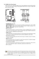
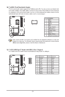
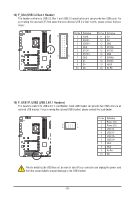
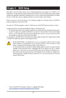
_ _ _B _ S_ 12) F_AUDIO (Front Panel Audio Header) _ The front panel audio header supports High Definition audio (HD). You may connect your chassis front panel audio module to this header. Make sure the wire assignments of the module connector match the pin assignments of the motherboard header. Incorrect connection between the module connector and the motherboard header will make the device unable to work or even damage it. _ Pin No. Definition 9 1 1 MIC L F_ U F_ 2 GND 10 2 3 MIC R 4 NC 5 Head Phone R _ S F_ 6 MIC Detection 7 SENSE_SEND 8 No Pin B S S_F B_ 9 Head Phone L 10 Head Phone Detection B SS B_ Some chassis provide a front panel audio module that has separated connectors on each wire 1 instead of a single plug. For information about connecting the front panel audio module that has different wire assignments, please contact the chassis manufac_tSurer. _ F _F _0 F_ _3 1 23 1 1 23 1 1 23 1 13) F_U32C (USB Type-C® HeadFe_r with USB 3F.S_2 Gen 2 Support) The header conforms to USB 3.2 Gen 2 specification and can provide one USB port. B_ USB 0_ B S3 1 23 S F_USB3 F_USB30 3 Pin No. Definition Pin No. Definition S 10 11 1 VBUS 11 VBUS 2 TX1+ 12 TX2+ 3 TX1- 13 TX2- 1 20 4 GND 14 GND 5 RX1+ 15 RX2+ 6 RX1- 16 RX2- 7 VBUS 17 GND 8 CC1 18 D- 9 SBU1 19 D+ B SS S 1U0 SBU2 20 CC2 __ 3 _ SF _ F_USB - 29 - B_ S _S _ _ _B _
-
 1
1 -
2
-
3
-
4
-
5
-
6
-
7
-
8
-
9
-
10
-
11
-
12
-
13
-
14
-
15
-
16
-
17
-
18
-
19
-
20
-
21
-
22
-
23
-
 24
24 -
 25
25 -
 26
26 -
 27
27 -
 28
28 -
 29
29 -
 30
30 -
 31
31 -
 32
32 -
 33
33 -
 34
34 -
35
-
36
-
37
-
38
-
39
-
40
-
41
-
42
-
43
 |
 |
