Haier AU42NAIBEA User Manual - Page 14
Test run, Trouble display
 |
View all Haier AU42NAIBEA manuals
Add to My Manuals
Save this manual to your list of manuals |
Page 14 highlights
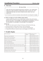
Installation Procedure Electric wiring 6. Test run CAUTION THIS UNIT WILL BE STARTED INSTANTLY WITHOUT "ON" OPERATION WHEN ELECTRIC POWER IS SUPPLIED.BE SURE TO EXECUTE "OFF" OPERATION BEFORE ELECTRIC POWER IS DISCONNECTED FOR SERVICING. This unit has a function of automatic restart system after recovering power stoppage. (1) Before starting test run (for all Heat pump models) Confirm whether the power source breaker (main switch) of the unit has been turned on for over 12 hrs to energize the crankcase heater in advance of operation. (For AU142AFBEA , AU182AFBEA, AU242AHBEA,AU282AHBEA, AU28NAHBEA, AU36NAIBEA, AU42NAIBEA, AU52NAIBEA) (2) Test run Run the unit continuously for about 30 minutes, and check the following. Suction pressure at check joint of service valve for gas pipe. Discharge pressure at check joint on the compressor discharge pipe. Temperature difference between return air and supply air for indoor unit. 7. Trouble display Failure description Room temp. sensor abnormal Indoor coil temp. sensor abnormal Outdoor temp. sensor abnormal Code on wired Flash times of indoor controller receiver board 01 Power LED flashes 1 time 02 Power LED flashes 2 times 4A Power LED flashes 3 times Outdoor coil temp. sensor abnormal 49 Over-current malfunction 48 High / Low pressure abnormal 53 Communication malfunction between indoor and wired controller 07 Communication malfunction between indoor and outdoor abnormal 06 Power LED flashes 4 times Power LED flashes 5 times Power LED flashes 6 times Power LED flashes 8 times Power LED flashes 9 times Drainage system malfunction Alarm of exterior annunciator Coil gas pipe temp. Sensor abnormal Temperature protection malfunction 08 Power LED flashes 10 times 0B Power LED flashes 11 times 03 Power LED flashes 12 times 0D Power LED flashes 13 times 13
-
 1
1 -
2
-
3
-
4
-
5
-
6
-
7
-
8
-
 9
9 -
 10
10 -
 11
11 -
 12
12 -
 13
13 -
 14
14
 |
 |