Haier DW12-LBE User Manual - Page 12
Installation, Diagram
 |
View all Haier DW12-LBE manuals
Add to My Manuals
Save this manual to your list of manuals |
Page 12 highlights
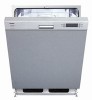
Installation 220-240V ~ Diagram A N IS B L C 1 1 2 3 12 3 4 5 6 7 8 CnL1 P O ISS N CnP3 1 2 3 4 5 6 7 8 CnP1 6 5 4 3 2 1 SCHEDA DI POTENZA e CONTROLLO CnP2 12 11 10 9 8 7 6 5 4 3 2 1 M RELE' D H D-ED F 1/2 G 1E 2 IAQS 3 2 J 4 M 1 ML 2 C S 1 AQS I 1 K L A.Wiring box B.Door switch C.Water level switch D.Drain motor E.Overflow switch F.Half wash switch G.Softer valve H.Dispenser valve I.Aquastop inlet valve J.Washing motor K.Temperature limiter L.Heater M.Relay N.Sensor temperature O.Salt missing switch P.Rinseing aid missing switch
-
 1
1 -
2
-
3
-
4
-
5
-
6
-
 7
7 -
 8
8 -
 9
9 -
 10
10 -
 11
11 -
 12
12
 |
 |

A.Wiring box
B.Door switch
C.Water level switch
D.Drain motor
E.Overflow switch
F.Half wash switch
G.Softer valve
H.Dispenser valve
I.Aquastop inlet valve
J.Washing motor
K.Temperature limiter
L.Heater
M.Relay
N.Sensor temperature
O.Salt missing switch
P.Rinseing aid missing switch
P
O
N
M
L
K
J
I
E
G
F
H
D
C
B
A
S
2
C
ML
1
4
M
1
AQS
2
3
1
IAQS
2
1
1/2
RELE'
3
1
2
5
4
6
10
8
9
CnP2
12
11
7
e
1
2
3
4
5
ISS
CnP1
5
6
7
1
2
3
4
8
CnP3
6
POTENZA
SCHEDA DI
CONTROLLO
D-ED
3
1
2
1
8
7
5
34
6
1
2
CnL1
IS
220-240V ~
N
L
Installation
Diagram