Haier DW9-CBE7 User Manual - Page 11
Notice
 |
View all Haier DW9-CBE7 manuals
Add to My Manuals
Save this manual to your list of manuals |
Page 11 highlights
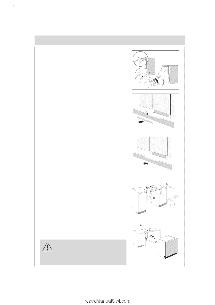
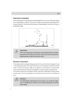
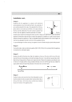
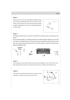
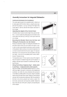
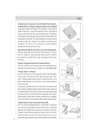
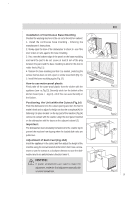
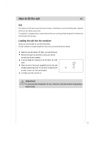
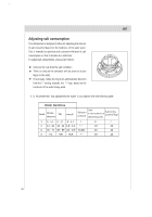
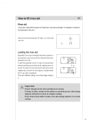
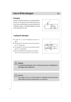
Installation of Continuous Base Moulding Position the washing machine in the cut-out in the kitchen cabinet: 1. Install the continuous base moulding , following the manufacturer's instructions . 2. Slowly open the door of the dishwasher to check to see if the door strikes or rubs against the base moulding. 3. If so, rest the bottom edge of the panel on the base moulding and mark the part to be cut. Leave at least 3 mm of the play between the panel and the base moulding to allow for the door to rotate freely (Fig.11). 4. Remove the base moulding and trim it as needed, protecting the surface that has been cut with a paint or similar wood finish (Fig.11). 5. Install the base moulding again (Fig.12). How to use water-proof plastic Firstly take off the water-proof plastic from the sticker with the appliance (see ¢æ, Fig.13). Secondly stick it on the bottom of the kitchen board (see ¢ , Fig.13). All of this can avoid humidity in the kitchen. Positioning the Unit within the Cutout (Fig.14) Push the dishwasher into the cutout opening and turn the feet to make it level and to adjust for height so that the crosspiece (A) for fastening it in place located on the top part of the machine (Fig.14) comes into contact with the counter .Align the door panel mounted on the dishwasher with the doors on the adjacent cabinet (2). Important: The dishwasher must absolutely be fastened to the counter top to prevent the machine from tipping when the loaded dish racks are pulled out. Adjustment of Back Feet (Fig.10A) Insert the appliance in the cutout and then adjust the height of the machine using the screws located at the bottom front .Use a screwdriver to turn the screws in a clockwise direction to raise the dishwasher and in an anticlockwise direction lower it. NOTICE: If power screwdrivers are used to make the adjustment, make the final adjustment manually with a normal screwdriver. en B A 2Kg 7Kg Fig.10 Fig.11 Fig.12 Fig.13 Fig.14 10
-
 1
1 -
2
-
3
-
4
-
5
-
 6
6 -
 7
7 -
 8
8 -
 9
9 -
 10
10 -
 11
11 -
 12
12 -
 13
13 -
 14
14 -
 15
15 -
 16
16 -
17
-
18
-
19
-
20
-
21
-
22
-
23
-
24
-
25
-
26
-
27
-
28
-
29
-
30
-
31
-
32
-
33
-
34
-
35
 |
 |