Haier HB4800VA1M25 User Manual - Page 13
Blower Performance
 |
View all Haier HB4800VA1M25 manuals
Add to My Manuals
Save this manual to your list of manuals |
Page 13 highlights
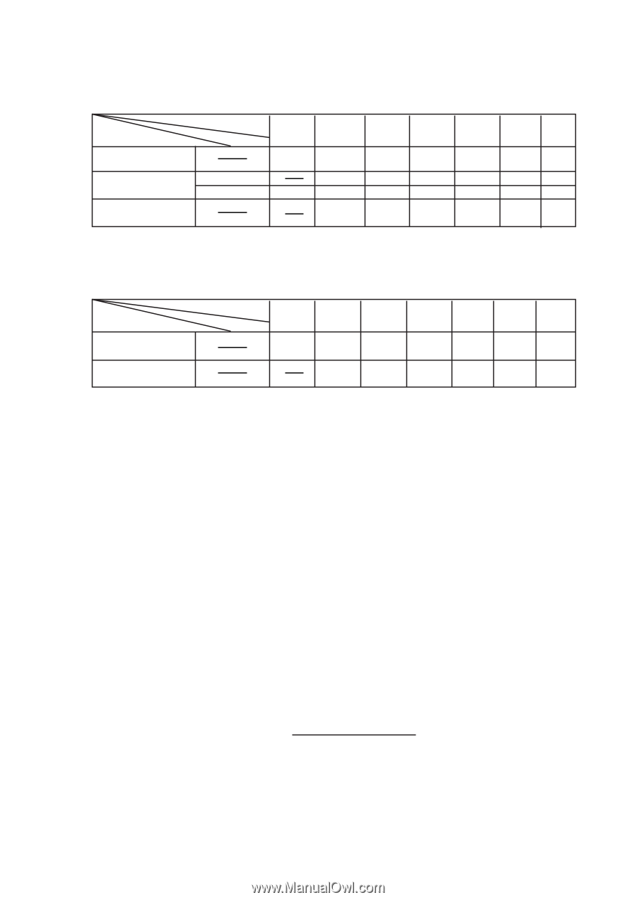
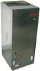
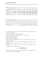
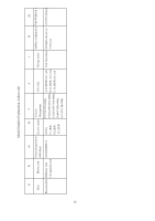
BLOWER PERFORMANCE CFM versus Static Pressure (inches of water column dry coil w/ filter) 4% reduction for wet coil. Static Pressure Model HB4200VA1M25 HB4800VA1M25 CFM High Middle HB6000VA1M25 0.15 1449 1449 0.2 0.25 0.3 0.35 0.4 0.5 1411 1701 1411 2063 1373 1656 1373 2008 1335 1611 1335 1953 1297 1566 1297 1259 1221 1518 1259 1470 1221 1898 1841 1784 Static Pressure Model CFM HB3600VC1M25 HB6000VC1M25 0.15 0.2 0.25 0.3 0.35 0.4 0.5 1276 1244 1213 1184 1157 1127 1097 2063 2008 1953 1898 1841 1784 The air delivery can be varied by changing the blower speeds. This can allow for differences encountered in installations. The CFM can be checked by the following method; (The optional Heat Kit must be installed to continue with this procedure.) 1) All access panels must be in place. 2) Start the unit in the heat mode. 3) Measure the return air temperature. 4) Measure the supply temperature. This measurement should be done in various locations to obtain an average. 5) Subtract the return temperature from the supply temperature. This is referred to as the temperature rise. 6) Measure the actual supply voltage and actual amperage at the terminal block/circuit breaker. 7) The BTUH output = (Voltage x Amps x 3.41) output (BTUH) CFM = 1.08 X temperature rise Should the CFM need to be increased or decreased it may be done by adjusting the blower speed tap as shown on the wiring diagram. 13
-
 1
1 -
2
-
3
-
4
-
5
-
6
-
7
-
 8
8 -
 9
9 -
 10
10 -
 11
11 -
 12
12 -
 13
13 -
 14
14 -
 15
15
 |
 |