Haier HB4800VA1M25 User Manual - Page 7
Downflow Instructions
 |
View all Haier HB4800VA1M25 manuals
Add to My Manuals
Save this manual to your list of manuals |
Page 7 highlights
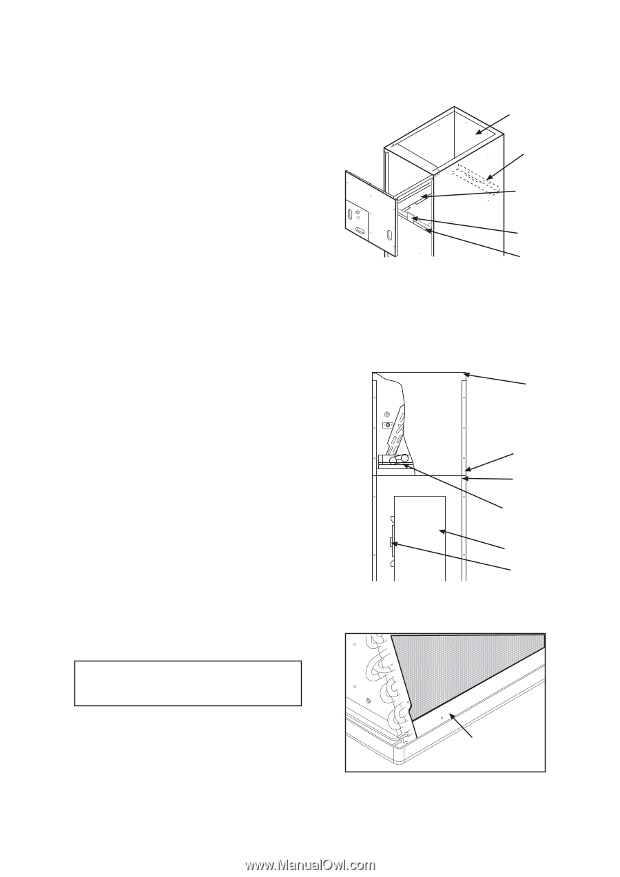
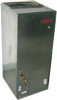
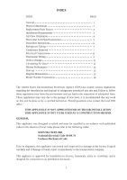
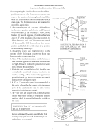
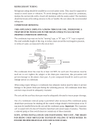
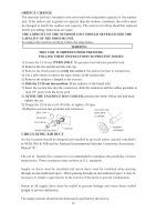
DOWNFLOW INSTRUCTIONS Important: Read instructions below carefully 1.Before putting the Air Handler in the downflow position, remove the three access panels and remove the metal coil retaining bracket and filter close off. Then remove the horizontal and vertical drain pans. The horizontal pan is not required for downfolw application 2.After removing the coil, turn the Air Handler to the downflow position and relocate the (8) brackets which include (1) tie bracket (1) rear channel bracket, (2) zee coil supports, (2) stiffener brackets, and (2) 3" 2 flat insulation retaining brackets. In effect, brackets, coil, and 2 lower access panels will be assembled 180 degrees from their former position and shifted down with return in up position as shown in fig.1 and fig.2. 3. Assemble drain pan insulation kit to the bottom of the drain pan to prevent drain pan from sweating during operation. 4. Place 3" flat insulation retainer on the bottom of each coil slab against the aluminum fins as shown in Fig.3. This will reduce the potential for water blow-off into the air stream. 5. Slide the coil assembly into Air Handler and reattach the metal coil retainer bracket to tie bracket. See Fig.2. Then reattach the upper access panel followed by the two lower access panels to match the tubing and drains. 6. A 4" to 3" removable panel is recommended at the point where the duct meets with the return part of the Air Handler unit to allow easier removal of coils that are too tall. 7. The "AD" coils are shipped with a check flowrator for use with either cooling or heat pump outdoor section which is accessible from the outside of the unit. AIR HANDLER UNIT RETURN AIR SIDE OF UNIT REAR CHANNELL BRACKET ZEE COIL SUPPORT BRACKET COIL RETAINING BRACKET TIE BRACKET NOTE: THE FIL TER PROVISION IS NOT APPLICABLE IN THIS DOWNFLOW APPLICATION Fig.1 Fig.2 TOP OF WRAPPER INSULATION JACKET ZEE COIL SUPPORT WRAPPER STIFFENER DRAIN PAN INSULATION DPI KIT (HATCHED AREA) BLOWER MOTOR WARNING: The "A" coil contains 150 p.s.i.g. of air pressure Before setting up flowrator assembly for field brazing see page 12 or read the Warning label on the lower access panel. Fig.3 3" FLAT INSULATION RETAINER (both sides) 7
-
 1
1 -
 2
2 -
 3
3 -
 4
4 -
 5
5 -
 6
6 -
 7
7 -
 8
8 -
 9
9 -
 10
10 -
 11
11 -
 12
12 -
13
-
14
-
15
 |
 |