Haier HL32R User Manual - Page 7
Connection Options
 |
UPC - 688057323480
View all Haier HL32R manuals
Add to My Manuals
Save this manual to your list of manuals |
Page 7 highlights
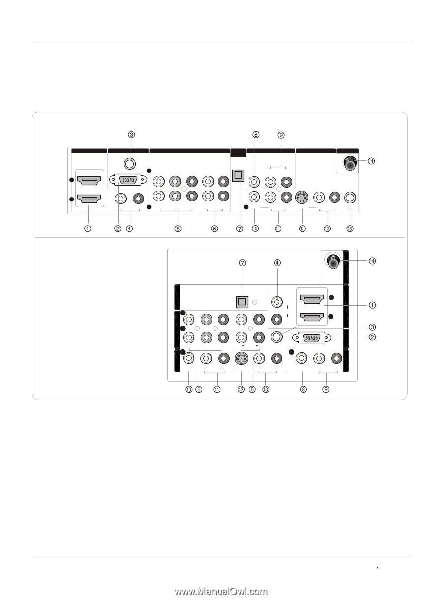
Connection Options Introduction Back panel controls HL26R,HL32R,HL40R,HL42R,HL42T,HL47T HDMI IN 2 1 VGA IN VGA AUDIO COMPONENT IN OPTICAL OUT AV OUT VGA 2 Y Pb Pr L-AUDIO- R VIDEO L-AUDIO-R VIDEO IN ANT IN L- DVI - R 1 Y Pb Pr AUDIO L-AUDIO- R 1 VIDEO L-AUDIO- R S-VIDEO L-AUDIO- R HL37T,HL52T ANT IN HDMI IN VIDEO IN COMPONENT IN OPTICAL OUT AV OUT VGA IN 2 L 2 DVI AUDIO 1 R 1 Y 1 Pb Pr L AUDIO R VGA AUDIO 1 VGA VIDEO L AUDIO R S-VIDEO L AUDIO R VIDEO L AUDIO R 1 HDM IN: Connect an HDMI signal to the jack. 2 VGA Video IN: Connect a video cable from a computer to the jack. 3 VGA Audio IN: Connect an audio cable from a computer to the jack. 4 DVI Audio IN: Connect a component video device to these jacks. 5 DVD/DTV IN(Component ): Connect a component video device to these jacks. 6 AUDIO IN(Component ): Connect the Audio L/R cables from the Component Video signal source these jacks. 7 Digital Audio Output: Connect digital audio from an external device. NOTE: In standby mode, these ports will not work. 8 VIDEO Out: Connect the second TV or monitor to the TV`s AV OUT. 9 AUDIO Out: Connect the audio L/R cables to the second TV`s AV IN. 10 VIDEO IN: Connects the video signal from a video device. 11 AUDIO IN: Connect the audio L/R cables from the Video signal source these jacks. 12 S-VIDEO IN: Connect the S-Video cable from an external signal source to the jack. 13 AUDIO IN: Connect the audio L/R cables from the S-Video signal source these jacks. 14 Antenna IN: Connect cable or antenna signals to the TV, either directly or through your cable box. 15 Headphone jack : Headphone audio output terminal. Owner s Manual 7
-
 1
1 -
 2
2 -
 3
3 -
 4
4 -
 5
5 -
 6
6 -
 7
7 -
 8
8 -
 9
9 -
 10
10 -
 11
11 -
 12
12 -
13
-
14
-
15
-
16
-
17
-
18
-
19
-
20
-
21
-
22
-
23
-
24
-
25
-
26
-
27
-
28
-
29
-
30
-
31
-
32
-
33
-
34
-
35
-
36
-
37
-
38
-
39
-
40
-
41
-
42
 |
 |