Haier HWM65-728A User Manual - Page 3
Names of the parts
 |
View all Haier HWM65-728A manuals
Add to My Manuals
Save this manual to your list of manuals |
Page 3 highlights
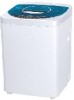
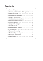
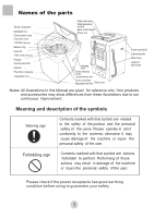
Ú Names of the parts Top lid component Detergent box Control panel seat Outer tub cover Lint filter(2 pieces) Water inlet valve Water absorption cushion Back control board Power line Balance ring Inner tub Filter cover(2 pieces) Pulsator Control panel film Cabinet Fixed foot (3 pieces) Adjustable foot Hanging hole Drain entrance cover Liquid whitener inlet Screw cover(right) Adjustable foot film Back cover Screw cover(left) Cabinet handle Drain hose Jacket of drain hose Notes: All illustrations in this Manual are given for reference only. Your products and accessories may show differences from these illustrations due to our continuous improvement. Meaning and description of the symbols Warning sign Contents marked with that symbol are related to the safety of the product and the personal safety of the users. Please operate in strict conformity to the contents, otherwise it may cause damage of the machine or injure the personal safety of the user. Forbidding sign Contents marked with that symbol are actions forbidden to perform. Performing of those actions may result in damage of the machine or injure the personal safety of the user. Please check if the power receptacle has good earthing condition before using to guarantee your safety. 1
-
 1
1 -
 2
2 -
 3
3 -
 4
4 -
 5
5 -
 6
6 -
 7
7 -
 8
8 -
 9
9 -
10
-
11
-
12
-
13
-
14
-
15
-
16
-
17
-
18
 |
 |
