Harbor Freight Tools 61169 User Manual
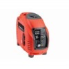
Harbor Freight Tools 61169 - 2500 Peak/2200 Running Watts Manual
 |
View all Harbor Freight Tools 61169 manuals
Add to My Manuals
Save this manual to your list of manuals |
Harbor Freight Tools 61169 manual content summary:
- Harbor Freight Tools 61169 | User Manual - Page 1
- Harbor Freight Tools 61169 | User Manual - Page 2
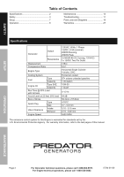
Safety 3 Setup 7 Operation 8 Maintenance 13 Troubleshooting 17 Parts Lists and Diagrams 19 Warranties 27 Protection Agency. For warranty information, refer to the last pages of this manual. OpERATION MAINTENANCE Page 2 For Generator technical questions, please call 1-888-866 - Harbor Freight Tools 61169 | User Manual - Page 3
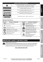
WARNING! Read all instructions. Failure to follow all instructions listed below may result in fire, serious injury and/or DEATH. The warnings and precautions discussed in this manual cannot cover all possible conditions and situations that may occur. It must be understood by the operator - Harbor Freight Tools 61169 | User Manual - Page 4
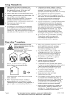
. If the plugged in product operates abnormally or unusually slow, immediately stop using the generator as a power source. Read and adhere to the instruction manual of the product to be powered to make sure that it can be safely and efficiently powered by a portable generator. 11. Before connecting - Harbor Freight Tools 61169 | User Manual - Page 5
34. Use the equipment, accessories, etc., in accordance with these instructions and in the manner intended for the particular type of equipment, may affect the equipment's operation. If damaged, have the equipment serviced before using. Many accidents are caused by poorly maintained equipment. 40 - Harbor Freight Tools 61169 | User Manual - Page 6
equipment is maintained. Do not attempt any service or maintenance procedures not explained in this manual or any procedures that you are uncertain while the smell of fuel hangs in the air. SAVE THESE INSTRUCTIONS. SETUp OpERATION MAINTENANCE Page 6 For Generator technical questions, please - Harbor Freight Tools 61169 | User Manual - Page 7
SAFETY SETUp Set Up Read the ENTIRE IMpORTANT SAFETY INFORMATION section at the beginning of this manual including all text under subheadings therein before set up or use of this product. TO pREVENT SERIOUS INJURY AND FIRE: Operate only with proper spark - Harbor Freight Tools 61169 | User Manual - Page 8
section at the beginning of this manual including all text under subheadings therein before set up or use of this product. pre-Start Checks Inspect Engine and Generator looking for damaged, loose, and missing parts before set up and starting. If any problems are found, do not use equipment - Harbor Freight Tools 61169 | User Manual - Page 9
Engine. b. Disconnect all electrical loads from the Generator. c. Fill the Engine with the proper amount and type of both unleaded gasoline and oil. Manual Start 1. Turn the Engine Switch on. 1 SETUp OpERATION 2 2. Move the Choke to the START position. 3. Turn the Fuel Valve to the ON position - Harbor Freight Tools 61169 | User Manual - Page 10
SAFETY 5. Allow the Engine to run for several seconds. Then, move the Choke Lever very slowly to its RUN position. Note: Moving the Choke Lever too fast could stall the Engine. 5 Move Slowly RUN START 6 IMpORTANT: Allow the Engine to run at no load for five minutes with no load after each - Harbor Freight Tools 61169 | User Manual - Page 11
resulting number is wattage. • Never exceed the running wattage for the Generator or any outlet amperage rating. • Refer to appliance/tool owner's manuals to determine the wattage of electrical load devices. • Long power cords and extension cords draw additional power. Keep cord length at a minimum - Harbor Freight Tools 61169 | User Manual - Page 12
Fuel Valve. ON OFF 3 Page 12 NOTICE Drain fuel at end of season or warranty is void. See Storage on page 16 for complete storage instructions. For Generator technical questions, please call 1-888-866-5797. For Engine technical questions, please call 1-800-520-0882. ITEM 61169 - Harbor Freight Tools 61169 | User Manual - Page 13
not use damaged equipment. If abnormal noise, vibration, or excess smoking occurs, have the problem corrected before further use. Follow all service instructions in this manual. The engine may fail critically if not serviced properly. Many maintenance procedures, including any not detailed in this - Harbor Freight Tools 61169 | User Manual - Page 14
SAFETY Checking and Filling Fuel WARNING! TO pREVENT SERIOUS INJURY FROM FIRE: Fill the fuel tank in a well-ventilated area away from ignition sources. If the engine is hot from use, shut the engine off and wait for it to cool before adding fuel. Do not smoke. 1. Clean the Fuel Cap and the area - Harbor Freight Tools 61169 | User Manual - Page 15
SAFETY SETUp Air Filter Element Maintenance 1. Remove the Access Panel on the side of the Generator. 2. Remove the Air Cleaner Cover and the air filter elements and check for dirt. Clean or replace as described below. 3. Cleaning: • For "paper" filter elements: To prevent injury from dust and - Harbor Freight Tools 61169 | User Manual - Page 16
SAFETY Storage When the equipment is to remain idle for longer than 20 days, prepare the engine for storage as follows: 1. CLEANING: Wait for engine to cool, then clean engine with dry cloth. NOTICE: Do not clean using water. The water will gradually enter the engine and cause rust damage. Apply a - Harbor Freight Tools 61169 | User Manual - Page 17
SAFETY SETUp Troubleshooting problem possible Causes Engine will not start FUEL RELATED: 1. No fuel in tank not remedy problem, replace head gasket. 4. Have qualified technician adjust/ repair valves and tappets. Follow all safety precautions whenever diagnosing or servicing the generator or - Harbor Freight Tools 61169 | User Manual - Page 18
not plugged in properly. doesn't have power 2. Circuit Breaker tripped. Attached device begins to operate abnormally 3. Product needs service. 1. Problem with device. 2. Running wattage exceeded. probable Solutions 1. Check wire connections. 2. Re-gap or replace spark plug. 3. Replace spark - Harbor Freight Tools 61169 | User Manual - Page 19
SAFETY SETUp parts Lists and Diagrams parts List and Diagram A - Crankcase part Description Qty 1a Left Crankcase Asm. 1 2a Oil Cork 1 3a Oil Sensor 1 4a Stand of Oil Sensor 1 5a Paper Washer 1 6a Dowel Pin 10×15.7 2 7a Stud 2 8a Dowel Axis 4 9a Bolt M6×17 2 10a Right - Harbor Freight Tools 61169 | User Manual - Page 20
add a -c suffix. SETUp OpERATION parts List and Diagram D - Camshaft part Description Qty 1d Screw, Pan Head 1 2d Oil Seal 15.2×1.5 1 3d Chain Guide 1 4d Chain 6.35×90 1 5d Tension Bar 1 6d Gasket 1 7d Camshaft Chain Regulator 1 8d Flange Bolt M6×22 2 9d Oil Ring 9×1.9 1 10d - Harbor Freight Tools 61169 | User Manual - Page 21
SAFETY parts List and Diagram E - Oil pump part Description Qty 1e Bolt M6×12 2 2e Oil Pump Gear Cap 1 3e Nut M6 1 4e Chain 6.35×44 1 5e Gear 1 6e Bolt 2 7e Oil Pump Asm. 1 Note: When ordering parts from this diagram add an -e suffix. SETUp OpERATION parts List and Diagram F - - Harbor Freight Tools 61169 | User Manual - Page 22
SAFETY SETUp parts List and Diagram G - Recoil Starter part Description Qty 1g Bolt M6×12 5 2g Recoil Starter 1 3g Fan Cover 1 4g Bolt M5×20 4 5g Fan Cover Bushing 4 6g Screw ST4.8×16-F.H 4 7g Recoil Cage 1 8g Cooling Fan 1 9g Shroud B 1 10g Shroud 1 11g Bolt M5×12 4 12g - Harbor Freight Tools 61169 | User Manual - Page 23
SAFETY parts List and Diagram I - Generator Head part Description Qty 1i Nut M12×1.25 1 2i Stator 1 3i Rotor 1 4i Bolt M5×40 2 5i Bolt M5×15 2 6i Trigger 1 7i Rubber Block 1 8i Bolt M6×25 1 9i Spark Plug 1 10i Ignition Asm. 1 11i Ignition Cap 1 Note: When ordering parts - Harbor Freight Tools 61169 | User Manual - Page 24
SAFETY SETUp parts List and Diagram K - Housing part Description Qty 1k Screw M6×12 5 2k Side Cover 1 3k Screw M6×20 2 4k Lift Cover 1 5k Protector Asm. 1 6k Protector Asm. Seal 1 7k Top Cover 1 8k Right Cover 1 9k Bolt ST4.2×13 1 10k Nut M8 8 11k Cover Plate 1 12k Bolt - Harbor Freight Tools 61169 | User Manual - Page 25
parts List and Diagram N - Inverter part Description Qty 1n Inverter Asm. 1 2n U Rack 1 3n Screw M6×12 2 4n Bolt M6×13 2 5n U Rack 1 6n Rubber Foot 2 Note: When ordering parts from this diagram add a -n suffix. SAFETY SETUp OpERATION parts List and Diagram p - Control panel part - Harbor Freight Tools 61169 | User Manual - Page 26
OpERATION MAINTENANCE pLEASE READ THE FOLLOWING CAREFULLY THE MANUFACTURER AND/OR DISTRIBUTOR HAS PROVIDED THE PARTS LIST AND ASSEMBLY DIAGRAM IN THIS MANUAL AS A REFERENCE TOOL ONLY. NEITHER THE MANUFACTURER OR DISTRIBUTOR MAKES ANY REPRESENTATION OR WARRANTY OF ANY KIND TO THE BUYER THAT HE - Harbor Freight Tools 61169 | User Manual - Page 27
for the performance of the required maintenance listed in your Owner's Manual. HFT recommends that you retain all receipts covering maintenance on your a HFT warranty station as soon as a problem exists. Contact the HFT Customer Service department at the number below to make shipping arrangements - Harbor Freight Tools 61169 | User Manual - Page 28
warranty station authorized by HFT. For emissions warranty service, contact the HFT Customer Service Department at 1-888-866-5797. 3. Consequential due to failure to follow the maintenance and operating instructions set forth in the Owner's Manual including, but not limited to: a) Use of parts
-
 1
1 -
 2
2 -
 3
3 -
 4
4 -
 5
5 -
 6
6 -
 7
7 -
8
-
9
-
10
-
11
-
12
-
13
-
14
-
15
-
16
-
17
-
18
-
19
-
20
-
21
-
22
-
23
-
24
-
25
-
26
-
27
-
28
 |
 |
