Harbor Freight Tools 61169 User Manual - Page 22
Parts List and Diagram G - Recoil Starter, Parts List and Diagram H - Muffler
 |
View all Harbor Freight Tools 61169 manuals
Add to My Manuals
Save this manual to your list of manuals |
Page 22 highlights
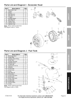
SAFETY SETUp parts List and Diagram G - Recoil Starter part Description Qty 1g Bolt M6×12 5 2g Recoil Starter 1 3g Fan Cover 1 4g Bolt M5×20 4 5g Fan Cover Bushing 4 6g Screw ST4.8×16-F.H 4 7g Recoil Cage 1 8g Cooling Fan 1 9g Shroud B 1 10g Shroud 1 11g Bolt M5×12 4 12g Shroud Bushing 4 13g Nut M5 2 Note: When ordering parts from this diagram add a -g suffix. parts List and Diagram H - Muffler part Description Qty 1h Gasket 1 2h Elbow 1 3h Nut M6 2 4h Gasket 1 5h Muffler Asm. 1 6h Bolt M6×80 1 7h Bolt M6×50 2 Note: When ordering parts from this diagram add a -h suffix. OpERATION MAINTENANCE Page 22 For Generator technical questions, please call 1-888-866-5797. For Engine technical questions, please call 1-800-520-0882. ITEM 61169
-
 1
1 -
2
-
3
-
4
-
5
-
6
-
7
-
8
-
9
-
10
-
11
-
12
-
13
-
14
-
15
-
16
-
 17
17 -
 18
18 -
 19
19 -
 20
20 -
 21
21 -
 22
22 -
 23
23 -
 24
24 -
 25
25 -
 26
26 -
 27
27 -
28
 |
 |

Page 22
For Generator technical questions, please call 1-888-866-5797.
For Engine technical questions, please call 1-800-520-0882.
ITEM 61169
SAFETY
OPERATION
MAINTENANCE
SETUP
Parts List and Diagram G - Recoil Starter
Part
Description
Qty
1g
Bolt M6×12
5
2g
Recoil Starter
1
3g
Fan Cover
1
4g
Bolt M5×20
4
5g
Fan Cover Bushing
4
6g
Screw ST4.8×16-F.H
4
7g
Recoil Cage
1
8g
Cooling Fan
1
9g
Shroud B
1
10g
Shroud
1
11g
Bolt M5×12
4
12g
Shroud Bushing
4
13g
Nut M5
2
Note:
When ordering parts from
this diagram add a -g suffix.
Parts List and Diagram H - Muffler
Part
Description
Qty
1h
Gasket
1
2h
Elbow
1
3h
Nut M6
2
4h
Gasket
1
5h
Muffler Asm.
1
6h
Bolt M6×80
1
7h
Bolt M6×50
2
Note:
When ordering parts from
this diagram add a -h suffix.