Harbor Freight Tools 61169 User Manual - Page 19
Parts List and Diagram A - Crankcase, Parts List and Diagram B - Piston
 |
View all Harbor Freight Tools 61169 manuals
Add to My Manuals
Save this manual to your list of manuals |
Page 19 highlights
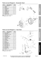
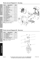
SAFETY SETUp parts Lists and Diagrams parts List and Diagram A - Crankcase part Description Qty 1a Left Crankcase Asm. 1 2a Oil Cork 1 3a Oil Sensor 1 4a Stand of Oil Sensor 1 5a Paper Washer 1 6a Dowel Pin 10×15.7 2 7a Stud 2 8a Dowel Axis 4 9a Bolt M6×17 2 10a Right Crankcase Asm. 1 11a Fuel Filter Asm. 1 12a Spring 1 13a Cap 1 14a O-Ring 1 15a Stud 2 16a Right Cover 1 17a Right Crankcase Gasket 1 18a Drain Plug 1 19a Oil Seal 19.8X30x5 1 20a Bolt M6×80 6 21a Bolt M6×90 2 22a Bolt M6×100 1 23a Bolt M6×50 2 Note: When ordering parts from this diagram add an -a suffix. parts List and Diagram B - piston part Description Qty 1b Crankshaft Asm. 1 2b Piston Pin Clip 2 3b Piston Pin 1 4b Piston 1 5b Piston Spacer Ring 1 6b Spacer Rails 2 7b Second Piston Ring 1 8b Top Piston Ring 1 9b Semicircle Key 1 Note: When ordering parts from this diagram add a -b suffix. OpERATION MAINTENANCE ITEM 61169 For Generator technical questions, please call 1-888-866-5797. For Engine technical questions, please call 1-800-520-0882. Page 19
-
 1
1 -
2
-
3
-
4
-
5
-
6
-
7
-
8
-
9
-
10
-
11
-
12
-
13
-
 14
14 -
 15
15 -
 16
16 -
 17
17 -
 18
18 -
 19
19 -
 20
20 -
 21
21 -
 22
22 -
 23
23 -
 24
24 -
25
-
26
-
27
-
28
 |
 |
