Harbor Freight Tools 62486 User Manual - Page 14
Preparing to Weld
 |
View all Harbor Freight Tools 62486 manuals
Add to My Manuals
Save this manual to your list of manuals |
Page 14 highlights
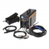
SAFETY CONTROLS BASIC WELDING Preparing to Weld Grounding Clamp TIG Torch 1. Connect components, as shown above. If Foot Pedal is to be used, connect as shown in "Foot Pedal (optional)" on page 13. Twist cables to lock in place. WARNING! To prevent serious injury and electric shock: Do not weld without Grounding Clamp. 2. Use a wire brush to thoroughly cleanse weldpiece of contaminants. 3. Consult fill material supplier's documentation to determine proper type and flow of shielding gas. Connect a hose and coupling from the gas regulator/flow meter on a shielding gas cylinder (all not included) to the shielding gas Inlet (5/8"-18 threads) on the back of the unit and adjust gas flow/PSI to proper level. Follow the gas cylinder manufacturer's instructions for set-up and use. Gas Inlet 4. The Gas Post Flow Delay Switch controls how long the shielding gas flows after the Trigger is released. Too little gas may make welds porous and create excessive spatter. Too much gas may waste gas. To conserve shielding gas switch it to "short". If the welded surface is being tarnished, change the switch to "long". Gas Post Flow Delay Switch Stick/TIG Switch Overload Light Current Output Knob 5. Turn the Current Output Knob to meet the needs of the job: higher amps for thicker material, lower amps for thinner material (refer to Settings Chart for more detail). 6. Move the Stick/TIG Switch to "TIG" (bottom position). 7. Plug the power cord into a grounded 240V/50A electrical socket and turn the Welder on. WARNING! TO PREVENT SERIOUS INJURY AND DEATH: The TIG Welder will immediately turn on when the trigger is held down. When the operator is not holding the Torch, it must be sitting on a nonconductive, nonflammable surface. WARNING! Only hold the filler rod using a thermally insulated welding glove. 8. Hold the Trigger down and begin welding. NOTICE: TIG welding is a complicated process, requiring experience and skill to achieve successful results. Training beyond the scope of this manual is required to TIG weld properly. 9. Move the torch in a small circle, creating a welding puddle. Keep filler material tip near the weld puddle. NOTE: Maintain a constant distance between the Electrode and the workpiece: between 1 and 1.5 times the diameter of the Electrode. 10. When welding puddle is hot enough, tilt torch backward about 10-15 degrees from vertical and move it back slightly. Add filler material as needed to the front end of the weld puddle. 11. Alternate between advancing the torch/ weld puddle and adding the filler material. NOTE: Remove the filler rod each time the electrode is advanced, but do not remove it from the gas shield. This prevents oxidation from contaminating the weld. 12. If duty cycle is reached, the Thermal Overload protector will activate, the Overload Light will turn on, and the welder will turn off until it cools down. If this happens, rest the electrode on an electrically non-conductive, heat-resistant surface, such as a concrete slab, well clear of the ground clamp. Wait about 8-10 minutes with the Power Switch to ON for the welder to cool. When the welder can be used again, use shorter welding periods and longer rest periods to help prevent needless wear. 13. When finished welding, release the trigger, but keep Torch on weld puddle until gas flow ends. Turn the Current Output Knob to the lowest setting, and turn the Power Switch off. WELDING TIPS MAINTENANCE Page 14 For technical questions, please call 1-888-866-5797. Item 62486
-
 1
1 -
2
-
3
-
4
-
5
-
6
-
7
-
8
-
 9
9 -
 10
10 -
 11
11 -
 12
12 -
 13
13 -
 14
14 -
 15
15 -
 16
16 -
 17
17 -
 18
18 -
 19
19 -
20
-
21
-
22
-
23
-
24
-
25
-
26
-
27
-
28
 |
 |
