Harbor Freight Tools 62519 User Manual - Page 6
Assembly/Mounting, Check and Align Bevel Scale Indicator
 |
View all Harbor Freight Tools 62519 manuals
Add to My Manuals
Save this manual to your list of manuals |
Page 6 highlights
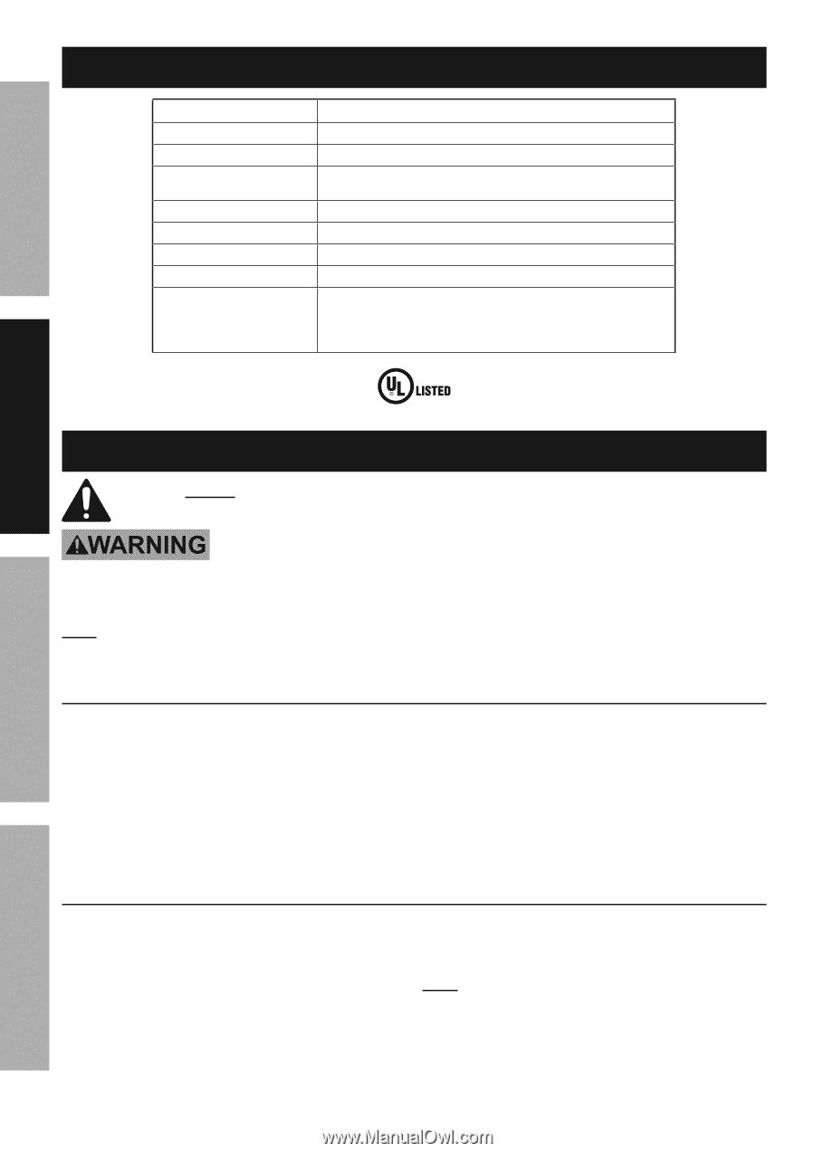
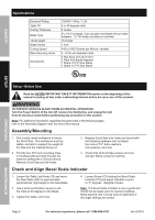
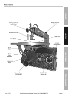
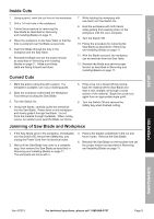
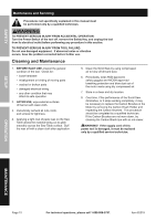
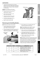
Safety Setup Specifications Electrical Rating Table Tilt Cutting Thickness Blade Type Throat Depth Blade Stroke Cutting Speed Base Mounting Holes Accessories 120VAC / 60Hz / 1.2A 0 to 45 degrees (left) 2 inches 5" L Pin End blade; Can use plain end blade with provided adapters. 15 TPI blade mounted on machine. 16 inches 1 inch 445 to 1600 Strokes per Minute; Variable 4 - 5/16 inch diameter holes 2 Hex Keys (2.5 and 4 mm) 2 Plain End Blade Adapters 1 Spare 18 TPI Saw Blade 1 Spare 15 TPI Saw Blade E154499 Setup - Before Use: Read the ENTIRE IMPORTANT SAFETY INFORMATION section at the beginning of this manual including all text under subheadings therein before set up or use of this product. TO PREVENT SERIOUS INJURY FROM ACCIDENTAL OPERATION: Turn the Power Switch of the tool off, remove the Safety Key, and unplug the tool from its electrical outlet before performing any procedure in this section. Note: For additional information regarding the parts listed in the following pages, refer to the Assembly Diagram near the end of this manual. Assembly/Mounting 1. Pick a solid, wood workbench to mount the Scroll Saw. The workbench must be stable, and able to support the weight of the Saw and the material being cut. 2. Find the four 5/16 inch mounting holes in the Base (89) and mark through the holes for drilling with a 3/8 inch drill bit. Remove Scroll Saw and drill holes. 3. Replace Scroll Saw over holes and mount with the following hardware (not included): four sets of 1/4″ bolts, washers, lock washers, and nuts. 4. Check that all Scroll Saw screws and nuts are tight before using the machine. Check and Align Bevel Scale Indicator 1. Loosen the Table Lock Knob (75) and move the Saw Table until it is approximately perpendicular (right angle) to the Saw Blade. 2. Use a small combination square to set the Table at 90 degrees to the Blade. 3. Tighten the Table Lock Knob. 4. Loosen Screw (72) holding the Bevel Scale Indicator (73) and adjust Indicator to point to "0" degrees. Retighten Screw. Note: The Bevel Scale Indicator is only a guide and should not be relied upon for precision settings. Make practice cuts in scrap wood to determine if the angle settings are correct. Operation Maintenance Page 6 For technical questions, please call 1-888-866-5797. Item 62519
-
 1
1 -
 2
2 -
 3
3 -
 4
4 -
 5
5 -
 6
6 -
 7
7 -
 8
8 -
 9
9 -
 10
10 -
 11
11 -
 12
12 -
13
-
14
-
15
-
16
 |
 |