Harbor Freight Tools 65345 User Manual - Page 15
Operating Instructions
 |
View all Harbor Freight Tools 65345 manuals
Add to My Manuals
Save this manual to your list of manuals |
Page 15 highlights
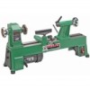
BALANCE WHEEL (22) HEADSTOCK SPINDLE (14) FIGURE N HEADSTOCK SPUR CENTER (12) OPERATING INSTRUCTIONS 1. With the Power Switch (46) in its "OFF" position and the Lathe unplugged from its electrical outlet, make all necessary adjustments to the machine as previously discussed. FACEPLATE (13) 2. To set up a spindle turning operation, mark both ends of the workpiece by drawing diagonal lines from corner to corner. The intersection point of these two lines will indicate the center of the workpiece. (See Figure O.) 3. The Power Switch Safety Switch: 1. The Lathe features a yellow Safety Switch on the Power Switch (46) to prevent unauthorized use. To turn 4. the Lathe on, plug the Power Cord (45) into the nearest 120 volt, ground- ed, electrical outlet. 2. Insert the Safety Switch into the Power Switch (46). Move the Power Switch to the "ON" position. To turn the Lathe off, move the Power Switch to the "OFF" position. To lock the Power Switch in the "OFF" position, remove the Safety Switch and store it in a safe location. (See Figure O.) Use a wood mallet and punch to tap the point of the center of the workpiece so that it leaves a center mark. (See Figure O.) Use a 1/8" drill bit to drill a 3/16" deep hole at the center mark on the workpiece. (See Figure O.) FIGURE O PENCIL LINES MARKED DIAGONALLY ACROSS CORNERS WORKPIECE FIGURE O 5. Cut the corners off the workpiece if it is over 2" x 2" to make turning safer and easier. (See Figure P.) FIGURE P POWER SWITCH (46) SKU 65345 For technical questions, please call 1-800-444-3353. Page 15
-
 1
1 -
2
-
3
-
4
-
5
-
6
-
7
-
8
-
9
-
 10
10 -
 11
11 -
 12
12 -
 13
13 -
 14
14 -
 15
15 -
 16
16 -
 17
17 -
 18
18 -
 19
19 -
 20
20 -
21
-
22
 |
 |
