Harbor Freight Tools 68147 User Manual - Page 8
Assembly
 |
View all Harbor Freight Tools 68147 manuals
Add to My Manuals
Save this manual to your list of manuals |
Page 8 highlights
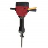
Safety Setup Specifications Electrical Rating Blows Per Minute Chisel Weight Other Accessories 120VAC / 60Hz / 15A 950 BPM 1 Bull Point (included) 1 Flat Chisel 71 lb 1 Grease Tube 1 Carbon Brush Set 4 Hex Keys (5, 6, 8, & 12mm) E252823 Setup - Before Use: Read the ENTIRE IMPORTANT SAFETY INFORMATION section at the beginning of this manual including all text under subheadings therein before set up or use of this product. TO PREVENT SERIOUS INJURY FROM ACCIDENTAL OPERATION: Make sure that the Trigger is in the offposition and unplug the tool from its electrical outlet before performing any procedure in this section. Note: For additional information regarding the parts listed in the following pages, refer to Parts List and Diagram on page 18. Assembly The only assembly required for the Breaker Hammer is the installing of the Secondary Handle (31) to the side of the Gear Cover (30). 1. Slot the base of the Secondary Handle into the recessed area of the Gear Cover. See Figure A. 2. Attach Secondary Handle to Gear Cover with Steel Bushings (31A) and Bolts (34). Gear Cover Secondary Handle Main Handle Steel Bushing Bolt Figure A Operation Maintenance Page 8 For technical questions, please call 1-888-866-5797. Item 68147
-
 1
1 -
2
-
 3
3 -
 4
4 -
 5
5 -
 6
6 -
 7
7 -
 8
8 -
 9
9 -
 10
10 -
 11
11 -
 12
12 -
 13
13 -
14
-
15
-
16
-
17
-
18
-
19
-
20
 |
 |
