Harbor Freight Tools 69738 User Manual - Page 6
Handle Setup
 |
View all Harbor Freight Tools 69738 manuals
Add to My Manuals
Save this manual to your list of manuals |
Page 6 highlights
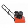
Safety Specifications Operating Speed Maximum Shock Force Vibration Frequency Maximum Performance Engine Type Plate Size Weight 0-82 FPM 3,000 lb 5,500 Vibrations Per Minute 350 m2 /hr 179cc 16-1/2″ x 22″ 176 lbs. Note: Additional specifications found in the Technical Engine Specifications chart in this manual. The emission control system for this Vibrator's Engine is warranted for standards set by the U.S. Environmental Protection Agency. For warranty information, refer to the last pages of this manual. At high altitudes, the engine's carburetor, governor (if so equipped), and any other parts that control the fuel-air ratio will need to be adjusted by a qualified mechanic to allow efficient high‑altitude use and to prevent damage to the engine and any other devices used with this product. Setup Operation Setup Read the entire Important Safety Information section at the beginning of this manual including all text under subheadings therein before set up or use of this product. To prevent serious injury from accidental operation: Turn the Power Switch of the equipment off, wait for the engine to cool, and unplug the spark plug wire(s) before assembling or making any adjustments to the tool. To prevent serious injury from accidental fires: Operate only with proper spark arrestor installed. Operation of this equipment may create sparks that can start fires around dry vegetation. A spark arrestor may be required. The operator should contact local fire agencies for laws or regulations relating to fire prevention requirements. Note: For additional information regarding the parts listed in the following pages, refer to Parts Lists and Diagrams on page 18. Handle Setup 1. Loosen the Knob Handle (31) on each side of the Upper Handle (32). 2. Swing the Upper Handle until it points straight out from the Lower Handle (29). 3. Tighten both Knob Handles (31) securely. Knob Handles (31) Upper Handle (32) Page 6 Lower Handle (29) For engine technical questions, please call 1-800-520-0882. For other technical questions, please call 1-800-444-3353. Item 69738 Maintenance
-
 1
1 -
 2
2 -
 3
3 -
 4
4 -
 5
5 -
 6
6 -
 7
7 -
 8
8 -
 9
9 -
 10
10 -
 11
11 -
 12
12 -
13
-
14
-
15
-
16
-
17
-
18
-
19
-
20
-
21
-
22
-
23
-
24
 |
 |
