Harbor Freight Tools 94282 User Manual - Page 4
Assembly
 |
View all Harbor Freight Tools 94282 manuals
Add to My Manuals
Save this manual to your list of manuals |
Page 4 highlights
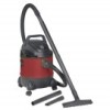
SAFETy SETUp Specifications Electrical Rating Tank Capacity 120V~ / 60Hz / 8A 5 Gallon 3084514 Setup - Before Use: Read the ENTIRE IMpORTANT SAFETy INFORMATION section at the beginning of this manual including all text under subheadings therein before set up or use of this product. TO pREVENT SERIOUS INJURy FROM AccIDENTAL OpERATION: Turn the power Switch of the appliance off and unplug the appliance from its electrical outlet before performing any procedure in this section. Note: For additional information regarding the parts listed in the following pages, refer to the Assembly Diagram near the end of this manual. Assembly 1. Open the Latch (3) located on each side of the Tank (5). See Figure A. Upper clasp Screw Figure A 2. Lift and remove the Power Head (2) from the Vacuum Blower. Then, turn the Tank upside down. 3. Insert the four Caster Assemblies (6) into the slots located at the bottom of the Tank. caster Support Figure B 4. Secure the Caster Assemblies to the Tank Base, using one Screw for each Caster Assembly. See Figure B. 5. Turn the Tank right side up so that it rests upon its four Casters. 6. Remove any stored parts from the Tank before use. OpERATION MAINTENANcE Page 4 For technical questions, please call 1-800-444-3353. Item 94282


