Harman Kardon AVR 8000 Owners Manual - Page 6
Front Panel Controls - receiver
 |
View all Harman Kardon AVR 8000 manuals
Add to My Manuals
Save this manual to your list of manuals |
Page 6 highlights
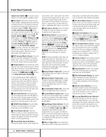
Front Panel Controls Digital Select Button Ú, this button may be pressed to scroll through the available options. 8 Tone Mode: This button controls the tone control settings, enabling adjustment of the bass and treble boost/cut or the removal of the tone controls from the signal path. The first press of the button displays a TONE IN message in the Main Information Display ˆ. If you wish to take the tone controls to "flat," without any treble or bass alteration, press the ‹ or › Selector Buttons 7$ so that TONE OUT appears in the Lower Display Line B. To change the tone settings, press the button until either TREBLE or BASS appears in the Lower Display Line B as desired, and then press the ‹ or › Selector Buttons 7$ to increase or decrease the setting. Note that the Tone settings apply only to the front left and right speakers, and they are not in effect when a THX mode is in use. 9 DSP Surround Mode Selector: Press this button to select the following DSP Surround Modes: Hall 1, Hall 2 or Theater. (See page 28 for more information about surround modes.) ) Tuning Selector: Press the left side of the button to tune lower-frequency stations and the right side of the button to tune higher-frequency stations. When a station with a strong signal is reached, the TUNED Indicator I will be lit in the Main Information Display ˆ. To tune manually, tap the button lightly and note that the tuner will step up one frequency increment per button press. When the button is held for a few seconds you will note that the unit will quickly search the frequency band. Release it once the fast tuning starts; the tuner will automatically scan for the next station with an acceptable signal and then stop. ! Tuner Band Selector: Pressing this button will automatically switch the AVR 8000 to the Tuner mode. Pressing it again will switch between the AM and FM frequency bands. (See page 33 for more information on the tuner.) @ 6Ch/8Ch Direct Button: Press this button to select the 6-Channel Direct or 8-Channel Direct inputs as the AVR 8000's source. # Preset Station Selector: Press this button to scroll up or down through the list or stations that have been entered into the preset memory. (See pages 33 and 34 for more information on tuner programming.) $ Stereo Mode Selector/› Button: Pressing this selector button cycles through the stereo modes, and it is also used to turn off all surround processing and place the unit in a traditional two-channel Stereo mode. The first press selects 5-Channel Stereo, the next press selects 7-Channel Stereo, and the third press selects "SURROUND OFF," which is true Stereo. % Input Source Selector: Press this button to change the input by scrolling up or down through the list of input sources. ^ FM Mode Selector: Press this button to select Auto or Manual tuning. When the button is pressed so that the AUTO Indicator J lights, the tuner will search for the next station with an acceptable signal when the Tuning Selector )ué is pressed. When the button is pressed so that the AUTO Indicator J is not lit, each press of the Tuning Selector )ué will increase the frequency. (See page 33 for more information on using the tuner.) NOTE: The front panel digital audio, video and analog audio input and output jacks are normally concealed behind a drop-down door in the lower right corner of the front panel. To access these jacks, open the panel door by gently pulling down the upper right corner of the door as indicated by "PULL/OPEN." & Optical Digital 4 Input Jack: Connect the optical digital output of an audio or video product to this jack. * Optical Digital 4 Output Jack: Connect this jack to the optical digital input of a digital recorder to send a feed of the digital output when a PCM digital input source is in use by the AVR 8000. ( Coaxial Digital 4 Input Jack: Connect the output of a digital audio source to this jack. Ó Coaxial Digital 4 Output Jack: Connect this jack to the coaxial digital input of a digital recorder to send a feed of the digital output when a PCM digital input source is in use by the AVR 8000. Ô Input/Output Status Indicator: This LED indicator will normally light green to show that the front panel Video 5 Input Jacks are operating as inputs. When these jacks are configured for use as an output, the indicator will turn red to show that the jack may be used for recording. (See page 34 for more information on configuring the front panel jacks as outputs, rather than inputs.) Video 5 Input Jacks: These audio/video jacks may be used for temporary connection to video games or portable audio/video products such as camcorders and portable audio players. Ò DTS Neo:6 Mode Selector: Pressing this button selects one of the DTS Neo:6 modes. The first press selects the Neo:6 Movies mode, and a second press will select the Neo:6 Music mode. (See page 28 for more information on the Neo:6 modes.) Ú Digital Select Button: When playing a source that has a digital output, press this button to select between the Optical &e and Coaxial (b Digital inputs. (See page 31 for more information on digital audio.) Û DTS Surround Mode Selector: Pressing this selector button cycles the AVR through the DTS surround modes. The choice of available DTS modes will vary according to the type of program source material (DTS 5.1 or DTS 6.1) and whether your system is configured for 5.1 or 6.1/7.1 channel operation. Ù Volume Control: Turn this knob clockwise to increase the volume, counterclockwise to decrease the volume. If the AVR 8000 is muted, adjusting volume control will automatically release the unit from the silenced condition. ı Input Indicators: A green LED will light to the left of the input that is currently the input source for the AVR 8000. ˆ Main Information Display: This display delivers messages and status indications to help you operate the receiver. (See page 7 for a complete explanation of the Information Display.) ˜ Remote Sensor Window: The sensor behind this window receives infrared signals from the remote control. Aim the remote at this area and do not block or cover it unless an external remote sensor is installed. ¯ Surround Mode/Bitstream Indicators: These LEDS will light to show the surround mode and digital bitstream in use. Note that depending on the specific combination of input sources and surround mode selected, more than one indicator may light. (See page 32 for more information.) 6 FRONT PANEL CONTROLS
-
 1
1 -
 2
2 -
 3
3 -
 4
4 -
 5
5 -
 6
6 -
 7
7 -
 8
8 -
 9
9 -
 10
10 -
 11
11 -
 12
12 -
13
-
14
-
15
-
16
-
17
-
18
-
19
-
20
-
21
-
22
-
23
-
24
-
25
-
26
-
27
-
28
-
29
-
30
-
31
-
32
-
33
-
34
-
35
-
36
-
37
-
38
-
39
-
40
-
41
-
42
-
43
-
44
-
45
-
46
-
47
-
48
-
49
-
50
-
51
-
52
-
53
-
54
-
55
-
56
-
57
-
58
-
59
-
60
 |
 |
