Harman Kardon AVR 8000 Owners Manual - Page 8
Rear Panel Connections - specifications
 |
View all Harman Kardon AVR 8000 manuals
Add to My Manuals
Save this manual to your list of manuals |
Page 8 highlights
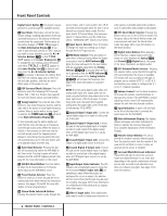
Rear Panel Connections 33 31 j h f 34 32 kig e db c · a° ‡ ¡ fl ™ fi £ ∞ › ¢ ¢ ∞ ¡ AM Antenna ™ FM Antenna £ Tape Outputs ¢ Front Speaker Outputs ∞ Surround Speaker Outputs § Subwoofer Output ¶ Amplifier Inputs • Main Channel Preamp Outputs ª CD Inputs , Surround Back Preamp Outputs ⁄ Tape Inputs ¤ Component Video Outputs ‹ Video 1/Video 2 Component Video Inputs › DVD Component Video Inputs fi AC Power Cord Jack fl Unswitched AC Accessory Outlet ‡ Switched AC Accessory Outlets ° Center Speaker Outputs · 8-Channel Direct Inputs a Coaxial Digital Audio Output b Coaxial Digital Inputs c 6-Channel Direct Inputs d Optical Digital Audio Output e Optical Digital Inputs f DVD Inputs g Amplifier Trigger Jack h Multizone IR Input i Remote IR Input j Remote IR Output k Video 1/Video 2 Inputs 31 Video 3/Video 4 Inputs 32 Multizone Outputs 33 Video 1/Video 2 Outputs 34 Video Monitor Outputs ¡ AM Antenna: Connect the AM loop antenna supplied with the receiver to these terminals. If an external AM antenna is used, make connections to the AM and GND terminals in accordance with the instructions supplied with the antenna. ™ FM Antenna: Connect the supplied indoor or an optional external FM antenna to this terminal. £ Tape Outputs: Connect these jacks to the RECORD/INPUT jacks of an audio recorder. ¢ Front Speaker Outputs: Connect these outputs to the matching + or - terminals on your left and right speakers. When making speaker connections always make certain to maintain correct polarity by connecting the color-coded (white for front left and red for front right) (+) terminals on the AVR 8000 to the red (+) terminals on the speakers and the black (-) terminals on the AVR 8000 to the black (-) terminals on the speakers. See page 15 for more information on speaker polarity. ∞ Surround Speaker Outputs: Connect these outputs to the matching + and - terminals on your surround channel speakers. In conformance with the new CEA color code specification, the Blue terminal is the positive, or "+" terminal that should be connected to the red (+) terminal on the Surround Left speaker with older color coding, while the Gray terminal should be connected to the red (+) terminal on the Surround Right speaker with the older color coding. Connect the black (-) terminal on the AVR to the matching black negative (-) terminals for each surround speaker. (See page 15 for more information on speaker polarity.) § Subwoofer Output: Connect this jack to the line-level input of a powered subwoofer. If an external subwoofer amplifier is used, connect this jack to the subwoofer amplifier input. ¶ Amplifier Inputs: When the jumper pins that link the Preamp Outputs • with these inputs are removed, these jacks may be used to connect an external source or the AVR 8000's multiroom system to the internal amplifiers. • Main Channel Preamp Outputs: When the jumper pins that link the Amplifier Inputs ¶ with these outputs are removed, these jacks may be connected to an external power amplifier. ª CD Inputs: Connect these jacks to the output of a compact disc player or CD changer. 8 REAR PANEL CONNECTIONS
-
 1
1 -
2
-
 3
3 -
 4
4 -
 5
5 -
 6
6 -
 7
7 -
 8
8 -
 9
9 -
 10
10 -
 11
11 -
 12
12 -
 13
13 -
14
-
15
-
16
-
17
-
18
-
19
-
20
-
21
-
22
-
23
-
24
-
25
-
26
-
27
-
28
-
29
-
30
-
31
-
32
-
33
-
34
-
35
-
36
-
37
-
38
-
39
-
40
-
41
-
42
-
43
-
44
-
45
-
46
-
47
-
48
-
49
-
50
-
51
-
52
-
53
-
54
-
55
-
56
-
57
-
58
-
59
-
60
 |
 |
