Harman Kardon CIT22 Owners Manual - Page 9
eakerCon, imippliirot,Conoec00.ff
 |
View all Harman Kardon CIT22 manuals
Add to My Manuals
Save this manual to your list of manuals |
Page 9 highlights
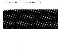
eakerCon Cabling. For optimal sonic performance, you should use the highest quality speaker cables you can afford. However, common "zip cord" from a hardware store can be employed if care is taken to use the proper gauge. This will depend on the distance from the Citation Power Amplifier to your speakers. Use the following chart as a guide: WIRE LENGTH GAUGE OF COPPER WIRE Upto 8 ft Up to 12 ft Up to 20 ft Up to 30 ft Up to 50 ft 18 gauge 16 gauge 14 gauge 12 gauge 10 gauge Make sure that both right and left speaker wires are about the same length, even if the distance from amp to each speaker is different. Also, avoid coiling any excess wire near or with audio cables, especially the sensitive cable from your turntable to the preamplifier. Connection. First, determine the polarity of your speaker wires. If you are using zip cord, they may 1) be different colors, such as silver and copper- colored, 2) have a series of ridges on one conductor, or 3) include a strand of yarn with one conductor. Note that the speaker terminals on your Citation Power Amplifier are marked Left and Right, with a corresponding Ground terminal for the negative speaker conductor below A good practice is to use the red/copper/ridged/ yarn conductor for the positive conductor on both amplifier and speaker terminal, and the black/silver/nonridged/no-yarn conductor for the negative (ground) connection. figure 1: Note bare wire strands spread around back of end post. 1. Strip 1/2 inch of insulation off the end of each speaker wire. 2. Completely unscrew and remove the end posts from all four Citation Power Amplifier speaker terminals. Note that each end post is hollow. 3. Taking care to maintain proper polarity (positive to positive/ negative to negative), insert the speaker wire into the center of each end post, so that half the length of the bare wire protrudes at the other end. 4. Now spread the individual wires in each conductor back around the end of the post. (See Figure 1) 5. Finally, screw the end posts firmly back into the terminal posts. Because the post surfaces are gold-plated, exceptionally good electrical contact will be made. ,s0.#*.i;Rorotii.okio0 Determining the impedance of your speakers. For proper performance, you must set the Speaker Operating Mode switch to correspond with the impedance load of your loudspeakers. There are a number of possibilities here: 1. You may know the impedance of your speakers. If so proceed to the next section. 2. If you dont know, it may be, A) printed on the back of the speaker, B) noted in the speaker's owner's manual, C) available by calling your dealer or the manufacturer. 3. If all these possibilities fail, you may be able to determine it yourself with an ohm meter. The actual impedance will be 20%-30% higher than the reading on the meter. However, this method will not work on transformer- coupled or capacitor-coupled loudspeakers. Setting the switches. If your speakers are rated at 4 or 6 ohms, set both switches to the top (4-ohm position). If you have 8-ohm speakers, set the switch to the lower (8-ohm position). Should you change speakers, or add extension speakers (which changes the overall impedance) you should reset the Speaker Operating Mode switch at that time. imippliirot,Conoec00.ff:: Again, we advocate using high quality connecting cables to get the most from your Citation Amplifier's extremely wide frequency bandwidth capabilities. Make sure that left preamplifier output is connected to the left Citation amplifier input, etc.
-
 1
1 -
2
-
3
-
 4
4 -
 5
5 -
 6
6 -
 7
7 -
 8
8 -
 9
9 -
 10
10 -
 11
11 -
 12
12
 |
 |
