Harman Kardon CITATION 15 Owners Manual - Page 6
Harman Kardon CITATION 15 Manual
 |
View all Harman Kardon CITATION 15 manuals
Add to My Manuals
Save this manual to your list of manuals |
Page 6 highlights
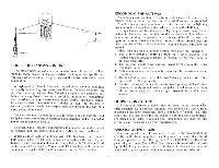
WATER TOWER O ANSMIT1 ER CHOICE OF TRANSMISSION LINE The major types of antenna lead-in wire available are flat ribbon, tubular, foam, coaxial and encapsulated. Each type has specific advantages which must be weighed against the costs involved in each installation. A high-quality 100-mil, 20-gauge, polyethylene 300-ohm twin-lead is usually satisfactory for most installations. Tubular or foam line provides better protection than flat ribbon against the elements and industrial smog. Coaxial lead-in is useful for multiple-set installations and to reduce pick-up of extraneous noise. Coaxial line has a higherloss characteristic than twin-lead (tubular or foam), but the loss is constant, and can easily be compensated for through the use of a more powerful antenna. The encapsulated 300-ohm line (also referred to as 300-ohm shielded lead) has excellent weather-resistant characteristics and a somewhat lower loss factor than coaxial. To avoid signal loss, the transmission line should be kept as short as possible and, preferably, should run vertically down to the set. When using an external antenna with 300 ohm twin lead, connect both leads to the two 300 ohm antenna terminals on the rear of your tuner. If your external antenna is connected with 75 ohm coaxial cable, connect between the 75 ohm and GND terminal, with the outer conductor or shield of the cable connected to the GND terminal. GROUNDING THE ANTENNA An antenna can act like a lightning rod because it is often the highest metal structure on the roof, It must therefore be grounded. Attach a heavy-gauge aluminum wire to the mast and a lightning arrestor to the transmission. line where it enters the building. On apartment-roof installations, a lightning arrestor may be attached to the mast, and another to the transmission line where it enters the building. In general, it is always advisable to keep the lightning arrestor outside the home interior. Where ground rods are used, they should be at least four feet long and deeply sunk into the ground. When selecting an FM antenna system remember the following: 1. The proper antenna should be used for a given location. The further you are located from the FM transmitter, the more gain the antenna inns t offer. 2. The antenna should have uniform signal level across the entire frequency range it covers. 3. Antenna placement is extremely important for maximum signal reception. 4. The installation must be rigid to avoid damage to the roof, chimney, wall or other property. 5. Careful routing of the lead-in line to avoid pick up of local interference. A poorly routed lead-in line (which touches metal portions of the house, etc.) will reduce signal strength by a significant margin. OUTPUT CONNECTONS The Citation Fifteen provides five different output receptacles, each designed for a specific function. One receptacle (Tape Out) is located on the front panel and uses a standard 1/4" phone jack. The other four, are located on the rear panel. All receptacles accept standard RCA phono jacks. In making your installation, you may use one or more pair, depending on your requirements. VARIABLE OUTPUT (L&R) These receptacles may be connected either to the preamplifier or directly to the basic amplifier. In either case, the level of signal at these receptacles is controlled by the GAIN CONTROLS on the front panel of your tuner. These Gain Controls may be used when adjusting the level of your tuner to match the level of other source material connected to your system, such as phonograph, tape recorder, etc. 5
-
 1
1 -
 2
2 -
 3
3 -
 4
4 -
 5
5 -
 6
6 -
 7
7 -
 8
8 -
 9
9 -
 10
10 -
 11
11 -
 12
12
 |
 |
