Harman Kardon CODA Owners Manual - Page 4
Kardon,lnc
 |
View all Harman Kardon CODA manuals
Add to My Manuals
Save this manual to your list of manuals |
Page 4 highlights
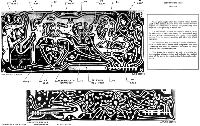
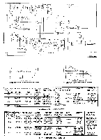
V6 I2AT7 VI \I2AT7 T2 V2 6BA6 T3 V3 T4 6AU6 V4 6AU6 CONSTRUCTION SHEET THE CODA * • • • 4,YRIGHT 3956 HAP k -KARDON,lNC REPRODUCTION FORBIDDEN T7 ▪ 'NO • li • • 'a.-3iR.ws 41f. S • • ANIENSIEW r 45ID I I * ■ s. *• • * • • •* • rfilempkt 0 • These photographs show the printed circuit boards used in the Harman-Kardon Coda and indicate to some degree the complexity of design and painstaking care required in the planning of such a unit. FM frequencies, by their very nature, require careful placement of parts and leads. In conventional point to point wiring, misplacement of a wire, even a slight amount from its correct position will adversely affect operation. The amplifier has been designed to use printed circuits in those areas where each component and each connecting lead must be carefully positioned in order to afford best possible operation. This design form results, we feel, in providing the best possible characteristics and reflects the highest state of the art in the construction of fine audio equipment. 0 • "IL TUNER SECTION /V7 6BE6 ELECTROLYTIC CAPACITOR T6 SELENIUM RECTIFIER T5 V5 6AL5 - s. MVO= P10'2:630 REPRODUCTION FORBIDDEN COPYRIGHT 1956 IN U.S.A. S. CANADA HARMAN-ICARDON, INC. ALL RIGHTS RESERVED . .. AMPLIFIER SECTION
-
 1
1 -
 2
2 -
 3
3 -
 4
4 -
 5
5 -
 6
6 -
 7
7 -
 8
8
 |
 |
