Harman Kardon HK210 Owners Manual - Page 7
Ventilation, Installation
 |
View all Harman Kardon HK210 manuals
Add to My Manuals
Save this manual to your list of manuals |
Page 7 highlights
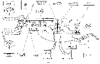
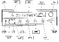
5 4 14 TOTAL 32 10 = 4I - -• 3 I MOUNTING SHELF -3 16 DIA (4 REVD) 12 MIN 14 176 MAX PANEL CUTOUT FOR CUSTOM MOUNTING 3 -31 MAX 32 1>>>>>> I • TOP VIEW FRONT PANEL ESCUTCHEON FRONT VIEW -1 MIN VENTILATION: Leave the back of the cabinet open. If this is not possible, provide several large holes or slots as low down and as high up in the cabinet back as possible. As an alternate, holes may be provided in the sides, bottom or top of the cabinet. Remember that really effective ventilation requires provision for cool air to enter at the bottom and hot air to leave at the top. A minimum clearance of two (2) inches should be allowed on each side and in the rear, between the chassis and the cabinet, and three (3) inches are required above it. Isolate any accessories which might interfere with ventilation or be affected by heat. For example, do not drape plastic or rubber covered interconnecting cable over the equipment. In some cases, it might be advisable to provide insulation (such as sheet asbestos) between the equipment and any other heat sensitive or heat producing device. INSTALLATION: 1. Locate and drill (4) 3/16" diameter holes on mounting shelf. 2. Position and cut out front panel opening. (Bottom of opening should be flush with top of mounting shelf.) 3. Remove (4) rubber feet from unit. (Rubber feet and screws are no longer used for cabinet installation). 4. Install unit from front through panel cutout opening. 5. Fasten unit to mounting shelf. If 1/2 " thick mounting shelf was used fasten with (4) #6 x 3/4 " long self-tapping screws and washers. If 3/4 " shelf was used fasten with (4) #6 x 1" long self-taping screws and washers. - 6 -
-
 1
1 -
 2
2 -
 3
3 -
 4
4 -
 5
5 -
 6
6 -
 7
7 -
 8
8 -
 9
9
 |
 |
